Browning Buckmark Reassembly

If you see something wrong or missing, or know a better way, or think a better photo is needed, please contact me.
These instructions were originally written by me Nov 2017 - Jun 2018. I retain the copyright to all words and photos on this page. © David Sutter 2017-2018

Browning Buck Mark Reassembly Steps (mainspring to whole gun)

Before you begin - How to use this web page - What year was my Buckmark made?, - Tools needed, - Why your parts might be different
  1. Install mainspring and mainspring plunger - put plunger into spring, drop into frame (plunger up), retain with 1/16" hex key
  2. Install hammer and safety lever - put them in the frame, line both up with frame hole, insert hammer pin left-to-right
  3. Install sear spring - lower spring into frame, position sear spring legs, pull it up, insert sear spring pin
  4. Install sear - push sear down onto front leg of sear spring, insert sear pin, reduced end first, right-to-left
  5. Remove mainspring retainer - overcock hammer and remove 1/16" hex key retaining the mainspring
  6. Install safety click plate - push safety click plate onto both the hammer pin and the sear pin
  7. Install slide stop - place slide stop on frame, ensure stop open latch spring tip is in the hole
  8. Install left grip (2-piece grips ONLY) - place on frame, under levers, over positioning pin, install grip screw
  9. Install magazine latch - drop into frame hole, skinny end first, tab into frame cutout
  10. Install magazine disconnector safety (if equipped) - insert mag, put bottom of wire in hole, lay wire into frame cutout
  11. Install v-shaped disconnector spring - front leg in frame cutout, open end up, sweep rear leg into place with finger
  12. Install disconnector - hook on mag disconnect safety, put angled tab behind spring, push forward, slip front onto pin
  13. Install T-shaped magazine latch spring - place in frame hole, arched up, on top of mag disconnect safety and mag latch
  14. Install right grip - OR - Install 1-piece wrap-around grips - one screw for right grip, more complicated for wrap-around grips
  15. Install slide - pre-2001 - OR - 2001-present
  16. Install barrel and top rail - anti-seize on barrel screw, barrel tab into frame, angle down, install all screws loosely, then tighten - OR - Install top rail only
  17. Test and lube your reassembled Buckmark - check the slide, extractor, mag release, safeties, trigger
  18. DONE! Go enjoy your Buckmark!


'Show/Hide Info' buttons are also available for each step to toggle showing or hiding extra info just for that step.

This page describes Buckmark reassembly only. If you are looking for disassembly steps, click here.

If you are looking for reassembly steps for a part not shown on this page, check the Sub-Assemblies page.
    includes Trigger, Extractor, Firing Pin (pre-2001 or 2001-present), Recoil Spring (pre-2001 or 2001-present), Magazine, and more.


Install Mainspring and Mainspring Plunger
  1. Insert the mainspring plunger into the mainspring (doesn't matter which end)
  2. Drop the mainspring and plunger into the frame, with plunger on top (see photo)
  3. Using a large punch (~1/8"), push the plunger cap down far enough to clear the mainspring retainer hole
  4. Slip a small metal rod through the mainspring retainer hole, above the top of the mainspring plunger.
    The metal rod could be a 1/16" punch or a 1/16" hex wrench, etc.
  5. Slowly release pressure on the punch until the mainspring is being held down by the metal rod
Mainspring (B5152478)
Mainspring Plunger (B5152580)
Drop in mainspring and plunger
Retaining the mainspring
Install Hammer and Safety Lever
Pre-requisites
  • If you separated the hammer link from the hammer, reattach the hammer link to the hammer with the hammer link pin.
    It can be tricky to get the parts lined up, so tap the pin partially into the hammer, insert the link, hold the link down with your finger, and push or tap the pin through carefully. When fully inserted, the pin should be flush with both sides of the hammer
  • If you removed the stop open latch spring from the hammer pin, slip it onto the hammer pin, at the groove.
    Looking at the end of the pin with the groove, the spring should be oriented so that both legs are pointing off to the left, the leg with the bent tip is the lower leg, with the bent tip facing you, and the top leg is curving away from you. (See photo)
Installation Steps
  1. Lay the frame down, with the left side facing up.
  2. Place the hammer in the frame with the cutout towards the rear, flat edge down, angled edge forward, the bottom of the hammer link in the cup at the top of the mainspring plunger, and the large hole in the hammer lined up with the hammer pin hole in the frame.
    If your hammer pin is tight in the frame, it may be easier to start by inserting the hammer pin from left to right, just enough so that it is held straight by the frame, but does not block insertion of the hammer. If it is loose in the frame, don't bother with this.
  3. Insert safety lever into the frame. Put the corner with the hole in first, below and in front of the hammer. See photo.
  4. Line up the hole in the safety lever and the hole in the hammer with the hammer pin hole in the frame.
  5. Push or tap the hammer pin in from left-to-right, capturing both the safety lever, and the hammer.
    The pin may not stay all the way in, because the stop open latch spring will push it back out a little. That's ok.
Hammer Pin & Stop Open Latch Spring
Hammer Orientation
Insert Safety Lever
Hammer and Safety Installed
Sear Spring Installation
There are several ways to install the sear spring. I have found the "zip tie" method described by user JEC in RFC thread 1057266 (post #8), to be the easiest.   The earliest reference to using a zip tie to install the sear spring is from March 7, 2017 in Thread 878210 by user redear, but he does not describe the usage in detail. Other methods are also outlined below.

Zip-tie method
JEC has made a you tube video showing this zip-tie method in action.
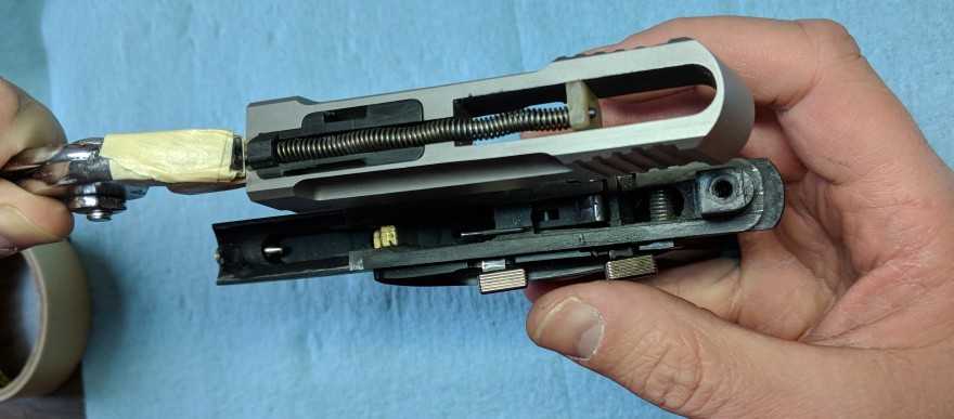
  1. Bend a zip tie into a U shape, and place it around the sear spring coils.
  2. Confirm sear spring orientation: long leg toward the front (always), and short leg toward the rear (always), legs at the top of the coils is the stock position, legs at the bottom of the coils is the "flipped" position.
  3. Holding the zip tie, lower the sear spring into the frame. Do not let go of the zip tie.
    Holding the zip tie lower/closer to the spring gives you better control.
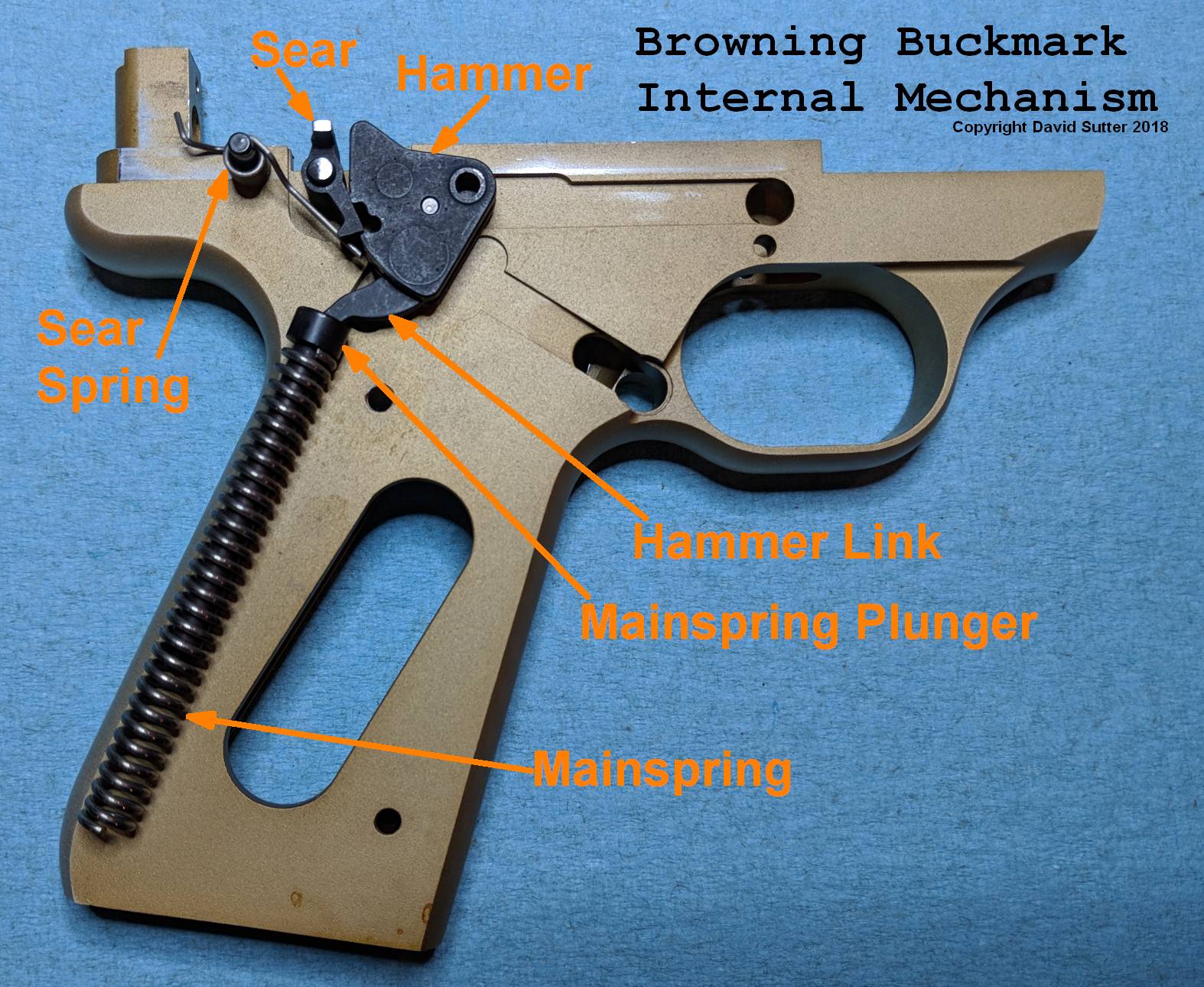
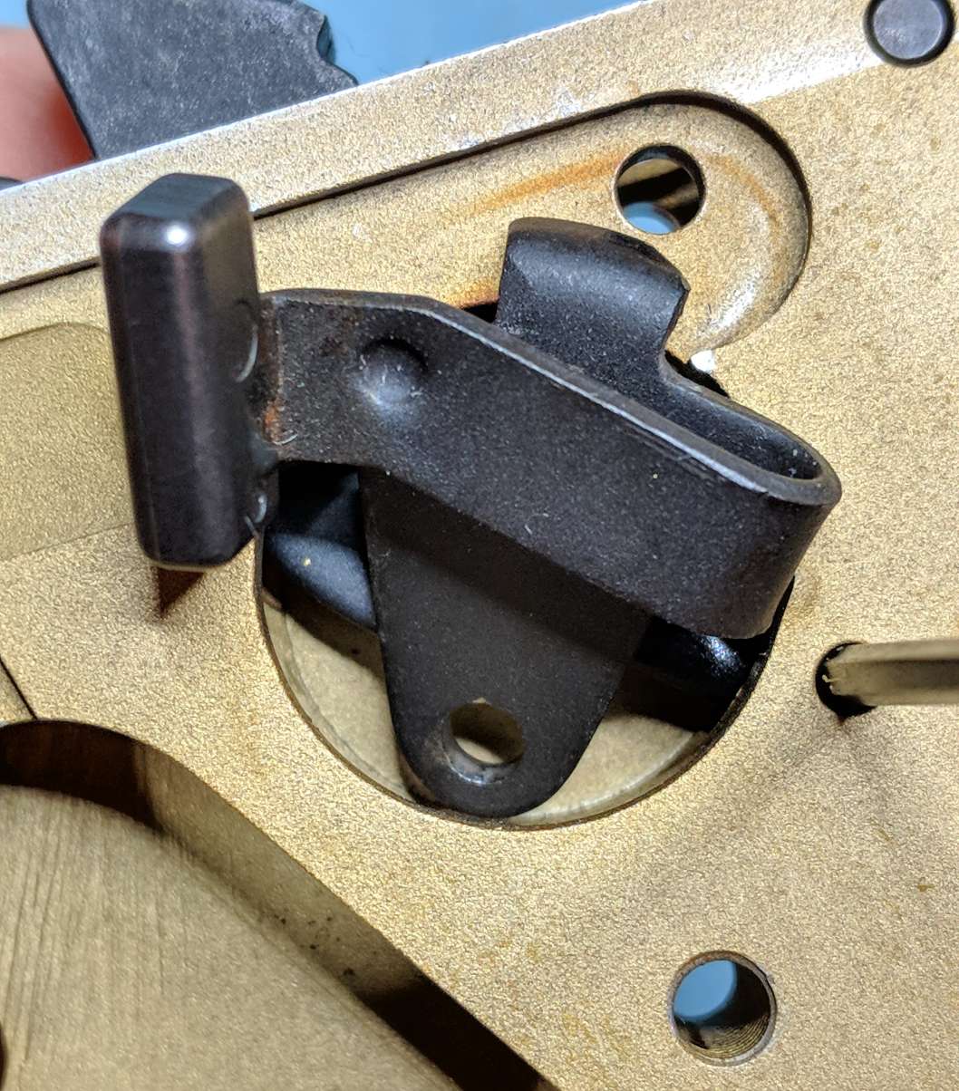
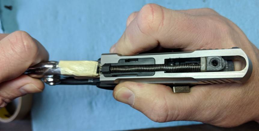
  4. Position the long front leg of the sear spring into the slot in the center of the hammer.
    You may need to rotate the hammer forward/up to expose the slot.
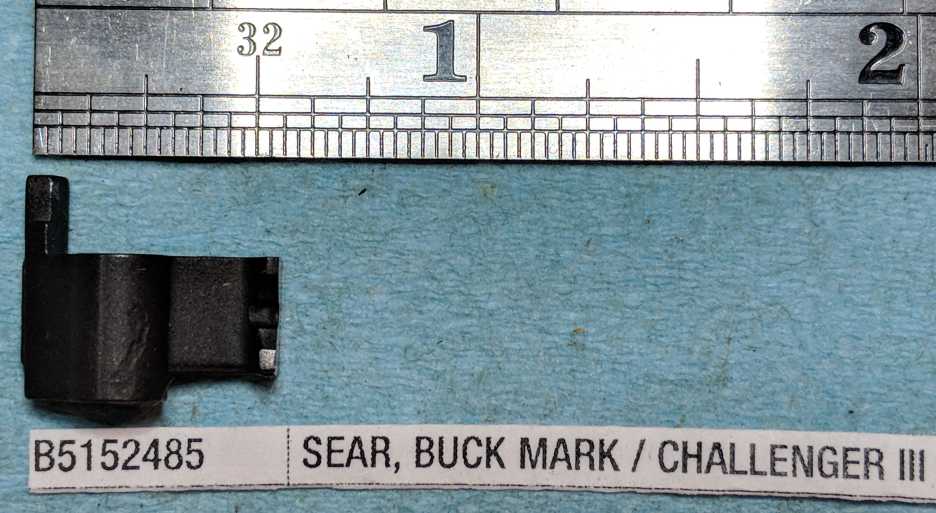
    If you are installing the sear spring while the sear is already in place, the front leg of the sear spring must go into the V-shaped notch at the bottom of the sear.
  5. Get the rear leg into place, using a small screwdriver or dental pick.
    Cutting a small v-notch in the end of the screwdriver can make this easier (tip from bandnuts).
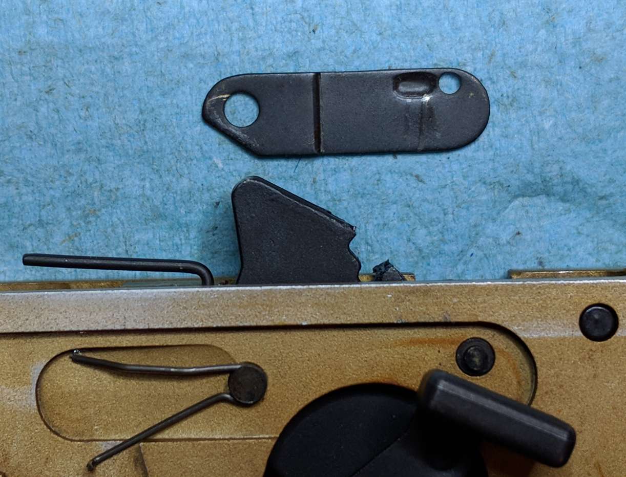
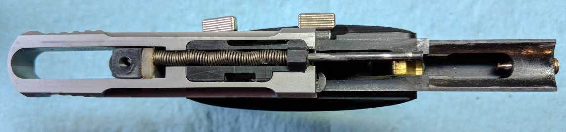
    • For Buckmarks with the sear spring adjusting screw, the bent-up tip of the rear leg of the sear spring must go into the bottom of the adjusting screw. (See photo)
    • For other Buckmarks, the rear leg must fit into the notch in the frame.
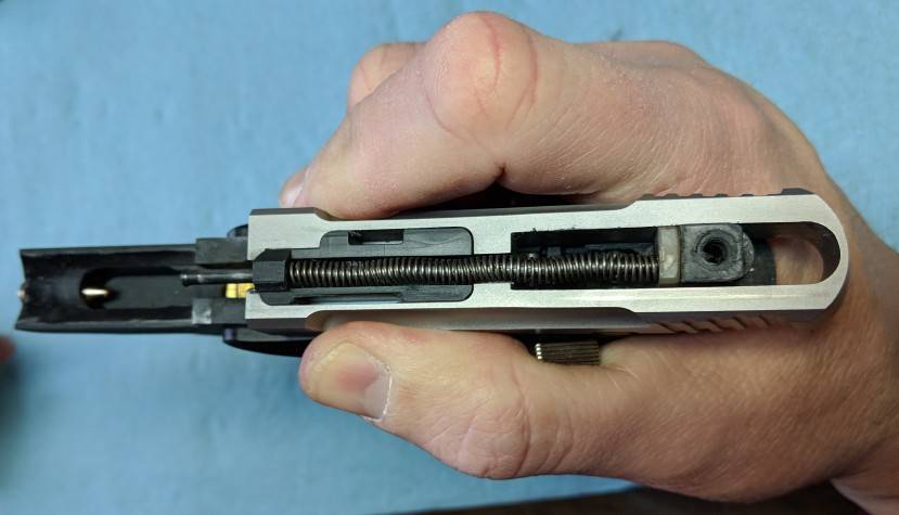
  6. Still holding both ends of the zip tie tightly, pull up on the zip tie, until the sear spring coils are lined up with the sear spring pin hole.
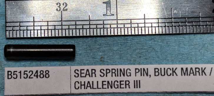
  7. Push the sear spring pin into the frame (either direction), and through the coils of the sear spring.
    The pin should be flush with both sides of the frame.
    One end of the pin may be beveled a little more than the other end. It's easier to insert the beveled end first, but it probably doesn't make a functional difference.
  8. Pull the zip tie out, confirm that the legs are still in their correct positions, and you're done.

Alternate method #1: Hold coils above frame, position legs, lower coils into position
It helps to start by putting the frame in a padded vice. Put a small (1/16") allen wrench through the coils and lay it on top of the frame, with the long leg forward, and the short leg towards the rear, and the coils approximately over the sear spring pin hole. Pull the short leg up, so that the long leg rotates down into the frame. Position the long leg in the v-shaped notch at the bottom of the sear. Holding the allen wrench to keep the spring in place, use small needle-nose pliers to grab the short rear leg and push it down into its position (usually in a notch in the frame). With both legs in position, begin pulling the allen wrench out of the coils, until one end is off the frame. Angle the allen wrench down, lowering the coils, until you can begin pushing the sear spring pin through the frame an into the coils. Push the pin in more as you slowly remove the allen wrench. Eventually the spring will be completely captured by the pin, and the allen wrench will be all the way out. Line up the pin with the frame hole on the far side, and push it the rest of the way into place. This method described in slightly different words in RFC Thread 922081 by user OCD

Alternate method #2: Insert sear spring into frame, then orient it and pull it up with a dental pick.
The basic idea is to drop the sear spring into the frame, and once it's down there, use a dental pick to get the legs into position, and then use the pick to lift the spring up so that you can slide the sear spring pin into place.
Although the idea is straightforward, the problem with this method is that most people find it infuriatingly difficult to actually do this.
Chim, in his instructions (on page 8) describes it this way: "Drop the sear spring into the frame and get it aligned with the pin holes. The pin has lots of clearance inside the coiled spring, so it isn't very difficult to line up"
This is also the method described by user varmithunter67 in RFC Thread 9612673 - Buckmark Trigger Work  - Post #439

Alternate method #3: Put a string through the coils first
Thread a piece of string through the coils (side-to-side), drop the sear into the frame, use a dental pick to position the legs, then use the string to pull the spring up into position, so that you can insert the sear spring pin. There is plenty of clearance inside the coils for the string and the pin at the same time. This makes the step where you lift the spring up into position MUCH easier than trying to do that with the dental pick, but I think the zip-tie method is better because it also has that advantage, plus the zip-tie can be used to help get the legs into position.

Alternate method #4: Partially insert the sear spring pin before positioning the legs
The basic idea is to get the sear spring captured before positioning the legs. Insert the spring into the frame long/front leg first, then insert the pin halfway to partially capture the sear spring. By only pushing the pin in part way, the sear spring still has some wiggle room. Then use a dental pick to force the rear/short leg down into place. Then drive the sear spring pin the rest of the way through. Perhaps this is possible on some Buckmarks, but on the 1992 Gold Target, I could not see how to do this without bending the rear leg of the sear spring pretty severely.

Alternate method #5: Install sear spring before the hammer
The basic idea is to install the sear spring first, then install the hammer/safety, then install the sear. This way, you only need to worry about getting the rear leg of the sear spring positioned correctly when installing the sear spring pin, and nothing else is in your way. Then, when installing the hammer, you push the hammer down onto the front leg of the sear spring. However, this method does make installing the hammer/safey more difficult, since the sear spring is trying to push the hammer out of position while you are trying to insert the hammer pin.

Why you should install the sear spring before the sear...
RFC POST from user BadaBing11 (from RFC thread 1009433):  Install the spring before inserting the sear. Then, install the sear, applying pressure to the spring with the sear. OMG, What a piece of cake that was. All the videos I've seen on youtube say to install the sear before the sear spring. I was at my wits end and darned near caved in to taking the gun to a gunsmith to get this done. I tried this suggestion and it took less than three minutes.
I wouldn't remove the sear just to install the sear spring, but if you have both out, definitely install the sear spring first, then the sear.

Notes on the Heggis Flip
The Heggis Flip is a common Buckmark modification intended to reduce trigger pull weight. It works because torsion springs (like the sear spring) offers more resistance when the legs are pushed in the direction that will tighten the coils, and offer less resistance when the legs are pushed in the direction that will loosen the coils. Torsion springs are intended to be used with the legs tightening the coils (they last longer this way, too). The stock orientation of the Buckmark sear spring is the normal/correct orientation of the spring. When flipped, the legs are being pushed in the direction that will loosen the coils, so it offers less resistance (reducing trigger pull weight).
The instructions for the Heggis Flip can be found at RFC post 1468180
That post is post #52 (page 4 or so) of  RFC thread 174356
When doing the Heggis Flip, you do NOT flip the spring front-to-back, you flip the spring top-to-bottom.
    In the stock configuration, the legs are at the top of the coils
    In the flipped configuration, the legs are at the bottom of the coils
    In either configuration, the long leg is always toward the front, and the short leg is always toward the back
    If you flip it such that the short leg is in the front, you will have failures (probably trigger reset issues)
Sear Spring Stock Orientation
Sear Spring Flipped Orientation
Zip Tie around Coils
Front leg in
Rear leg in Adjusting Screw
(Zip tie removed for photo clarity)
Sear Spring Pin (5152488)
Sear Spring Pin Installed
Sear Installation
  1. Rotate the hammer up/forward in the frame.
    If the hammer is down, the sear will catch on the hammer, and it will be almost impossible to line up the sear with its frame hole.
  2. With the sear oriented correctly (arm to the right, V-shaped notch at the bottom, facing the rear), put the V-shaped notch over the front leg of the sear spring.
  3. Push the sear down into the frame until it is lined up with its frame hole.
    You are pushing against the sear spring, so there will be some resistance, but not much force is required.
    The sear spring will actually help to keep it lined up and pushed forward, so it is relatively easy to line it up with its frame hole.
  4. Slide the sear pin in, reduced end first, from right-to-left, through the sear.
  5. Confirm that the front leg of the sear spring is still in the V-shaped notch at the bottom of the sear.
    If this leg is to the left or right of the sear, it will cause failures (trigger reset issues, mostly).

IMPORTANT: If installing a new or modified sear, confirm function of the safety lever!
If you are installing a new or modified sear, you need to understand that the tip of the left "leg" of the sear must be fit rather precisely to match the safety lever. When the safety lever is "all the way up" the top of the thumb piece should be parallel to and about even with the top of the frame.

Start with the hammer uncocked. If the safety lever can be moved all the way up when the hammer is uncocked, the left leg of the sear is too short, and the safety lever will not be able to prevent the sear from moving when the hammer is cocked and the trigger is pulled (which is what the safety is supposed to prevent). You either need to get a new sear, or try bending the safety lever.

Then cock the hammer, and try to push the safety lever up. It must be able to move all the way up, and the inward-bent part of the safety lever must be able to move up so that it is just behind the left leg of the sear. (See photo) If the safety lever cannot move up so that it is behind the sear, you need to file some off the tip of this leg, until it just fits (but no more).

Once the safety can be moved up into position, test that the sear cannot move backwards enough to release the hammer when the safety lever is up and the trigger is pulled. You can simulate a trigger pull by attempting to push the arm of the sear forward, but it should not move (except maybe a very small amount). If the sear moves enough to release the hammer when the safety is still up, the safety is not working as expected. You have filed too much off the front of the sear (probably in an effort to reduce creep), or you have filed too much off the back of the left leg of the sear. You either need to buy a new sear and start over, or you can attempt to bend the safety lever in a bit.

Now push the safety lever down. If the hammer falls when you do this, you have the same problem (too much filed off the sear), but arguably a more dangerous version of it.

Now bump and jostle the gun. If the hammer falls when you do this, you have the same problem (too much filed off the sear), but arguably an even more dangerous version of it.


IMPORTANT: If you flipped the sear spring, do the 'flick' test!
If you installed the sear spring in the flipped position, now that you have the sear in place, you should perform the 'flick' test to ensure that your sear spring is applying sufficient force to push the sear forward to catch the hammer.

With the hammer in the up/forward/uncocked position, pull the arm of the sear forward until it stops and then release it suddenly. This is best done with a dental pick, rather than your finger. (See photo)

The force applied by the sear spring should rotate the sear (top going back, bottom going forward) until it hits the hammer. The sear should hit the hammer with enough force that you can hear an audible click.

If you cannot clearly hear the sear hitting the hammer, your sear spring is either positioned wrong, or is too weak to force the sear to catch the hammer when the slide cycles. You need to fix this NOW. If left in this condition, you will have problems. Your trigger won't reliably reset, and/or your pistol will go full-auto. Both are bad.

RimfireCentral User LDBennett is an advocate of the Flick Test, and describes it this way:

Remove the slide. Cock the hammer. Hold the hammer to rear as far as it will go. With a probe flick the sear (push it forward and let the spring pressure alone seat the sear against the hammer) and listen for a noise from the sear hitting the hammer. No Noise? Then you have not got enough spring force to assure the sear catches the hammer in recoil. Re-adjust the spring and try agin. There must be an audible click of the sear hitting the held back hammer or the gun is not safe.


[Link to LD Bennett's description of the flick test.]

Sear (5152485)
Push Sear Down
Sear Pin (5152486)
Insert Sear Pin
Safety Lever behind Sear
Pulling Sear arm forward
(Simulates trigger pull)


Install the Safety Click Plate
  1. Slide the click plate under the safety lever, oriented with the large hole over the hammer pin, the small hole over the sear pin, and the cut-off part at the bottom-front.
    The click plate is not flat; the front end and back end are slightly offset. The front end (large hole) should be "raised", and back end (small hole) should be "lower".
  2. Push the front end of the click plate onto the hammer pin.
  3. Holding the frame in your hand, with your finger over the right side of the sear pin, press the click plate onto the sear pin. (I do this with the end of a punch, so I can push it straight down.)
    This should be fairly tight fit, so the click plate should sort of "snap" into position.
    Holding your finger over the right side of the sear pin prevents it from being pushed in by this action.
    Only the reduced portion of the sear pin will fit into the small hole on the safety click plate.
  4. Make sure the sear pin is flush with (or a little above) the top surface of the click plate. If not, keep trying. (See Photo)
  5. Make sure that the sear pin is flush with the frame on the right side, because it is easy to push it out a bit when installing the safety click plate.
    If the sear pin sticks out on the right side, it will interfere with the disconnector, and you will have issues (probably trigger reset issues).
  6. Make sure that the front of the click plate is still on the hammer pin.
Safety Click Plate Orientation
Safety Click Plate On Sear Pin
(but coming off the hammer pin)
Safety Click Plate Installed


Remove the metal rod holding back the mainspring
  1. Ensure that the bottom of the hammer link is in the "cup" that is the top of the mainspring plunger.
  2. Over-cock the hammer (push it down / back with your thumb as far as it will go).
    You will have to push down with significant force, to compress the strong mainspring.
  3. Pull out the metal rod that was holding the mainspring and mainspring plunger down.
  4. Slowly release pressure on the hammer, allowing it to rotate forward, as pushed by the mainspring.
If you installed a new hammer link, test it now.
If you installed a new hammer link (with a new hammer or separately), now is the time to confirm that it is not too long or too short.

A too-long hammer link will cause the trigger to not reset, because the hammer cannot rotate back far enough (when the slide cycles) to be caught by the sear (it will not stay cocked).
To test for a too-long hammer, start with the hammer in the up/forward/uncocked position. Place the slide onto the frame in the fully-forward position. It may be tight to get it down over the hammer, but it should go down into place with a small amount of force (which pushes the hammer back a little). Holding the frame in one hand, and holding the slide in the other hand, rack the slide (backward and then forward), keeping the slide down against the frame as it moves. The racking action should cock the hammer, and the hammer should stay cocked (held down by the sear). If the hammer does not stay cocked, your hammer link is too long. If the hammer link is too long, grind down the bottom of the hammer link to shorten it, or replace it with a shorter hammer link. If you grind it down, make sure the bottom tip is rounded and fairly smooth, so that it's movement inside the mainspring plunger cup is normal.

A too-short hammer link would result in light strikes, or in a more extreme case, allow the hammer link to come out of the mainspring plunger cap when the hammer is uncocked.
To test for a too-short hammer link, confirm that, with the hammer in the forward/uncocked position, any attempt to rotate it backwards (i.e. to begin to cock it), is immediately met with resistance from the mainspring. In other words, even when the hammer is uncocked, the mainspring should still be pushing on the hammer link.

Hammer Link in place
Overcocking the Hammer


Install Slide Stop Lever (a.k.a. Stop Open Latch Assembly)
NOTE: If your Buckmark has 1-piece wrap-around grips, you can skip this step, because it's just going to fall out when you turn the frame over to install parts on the right side. We'll do these steps as part of the grip installation process.
  1. Put both legs of the V-shaped stop open latch spring down inside the frame cutout. (See Photo)
  2. Place the slide stop down onto its frame hole, making sure that the bent-up tip of the lower leg of the V-shaped spring is sticking up into the hole in the slide stop. (See Photo)
Slide Stop Lever
(a.k.a. Stop Open Latch Assembly))
Stop Open Latch Spring
legs inside frame cutout
Spring leg in hole


Install Left Grip (on models with 2-piece grips)
Prerequisites
If you have removed the trigger or magazine ejector, you need to reinstall those before installing the left grip.

Installation
  1. Place the left grip onto the frame, with the top edge under the slide stop lever and safety lever, over the grip positioning pin, and lined up with the grip screw hole.
    On non-UDX Buckmarks, the magazine ejector retaining pin at the bottom-front of the grip frame serves as the grip positioning pin.
    On UDX Buckmarks, there is a separate pin near the back of the grip frame that serves as the grip positioning pin.
  2. Make sure the grip is flush with the frame on ALL sides.
  3. Screw in the grip screw.

Test the slide stop lever
Pull the slide stop lever up, and let it go. It should return to the down position. If it does not, the bent-up tip of the lower leg of the V-shaped stop open latch spring is not in the hole in the slide stop lever body. It is easy to accidentally knock the slide stop lever off the spring when installing the left grip. Remove the left grip, put the slide stop lever into place with the spring in the hole, and try again.

Grip Screws (side)
Grip Screws (head)
Left grip installation


Install magazine latch
  1. Lay the gun down, with the right side facing up.
  2. Drop the magazine latch into the frame hole behind the trigger.
    Skinny, serrated end first, tab towards the rear. It only fits one way.
Magazine latch
Drop in magazine latch


Install magazine disconnector safety (if equipped)
  1. Insert an empty magazine into the gun.
    You may need to hold the magazine latch down with your finger while you do this, so that it catches and holds the magazine in place.
    The toe of the magazine pushes the magazine ejector up and holds it there, exposing the hole.
  2. Insert the bottom of the magazine disconnector safety wire into the hole in the magazine ejector (which is inside the bottom of the grip frame).
  3. Lay the wire down into its frame cutout. No force is required. Do not bend the wire. Wiggle it, if necessary.
Magazine Disconnector Safety
Magazine Ejector hole
Drop wire into place


Install disconnector spring
  1. Lay one leg of the V-shaped disconnector spring into its frame cutout, with the bottom of the V (where the legs join) at the bottom of the frame cutout. (See Photo)
    The legs are the same, so it doesn't matter which one is which.
  2. Put your finger on the rear leg, and sweep it forward until it drops into the frame cutout
Disconnector Spring (B5150452)
One leg in the frame cutout
Sweep forward with finger
Disconnector Spring Installed


Install disconnector
  1. If your Buckmark has a magazine disconnector safety, lift up the top of it and hook it onto the disconnector
    Some disconnectors have a little cut out where the magazine disconnector safety wire goes, and some do not.
  2. Lay the disconnector in it's approximate location, with the downward-angled tab against the disconnector spring. The disconnector will not lay flat, because the sear arm is in the way. Angle the bottom edge down so that the tab is behind the disconnector spring.
  3. While pushing down lightly, slide the disconnector forward and slip the hole in the front of the disconnector over the disconnector pin. The disconnector can lay flat now, because the sear arm is lined up with the notch in the disconnector. It should just fall into place.
  4. Make sure both legs of the disconnector spring are down against the frame
    If the disconnector spring popped up while installing the disconnector, you can try to sweep the spring into place without removing the disconnector, or you can remove the disconnector, reinstall the disconnector spring, and then try installing the disconnector again.
Lay disconnector on frame
Disconnector installed


Install magazine latch spring
  1. Place the T-shaped magazine latch spring into its frame cutout, with the middle bowed out away from the frame. Wide end goes towards the back/top. The smaller end rests on the tab of the magazine latch.
    This spring is held in place by (and pushes against) the right grip.
    This spring keeps the magazine release button pushed to the left.
Magazine latch spring installed


Install right grip (for pistols with separate left-and-right grips)
  1. Lay right grip onto frame, over the grip positioning pin, and lined up with the grip screw hole.
    On non-UDX Buckmarks, the magazine ejector retaining pin at the bottom-front of the grip frame serves as the grip positioning pin.
    On UDX Buckmarks, there is a separate pin near the back of the grip frame that serves as the grip positioning pin.
  2. Make sure the grip is completely flush with the frame on ALL sides.
    There is a cutout on the inside of the grip that must be positioned over the disconnector pin (just above the trigger).
  3. Screw in the grip screw.
  4. Eject the magazine, if it was inserted to enable installation of the magazine disconnector safety.
Right grip installed


Install 1-piece wrap-around grips
  1. Concentrate on the left side first. Turn the frame over gently, so the left side is facing up. Don't worry if the T-shaped mag latch spring and/or mag latch falls out.
  2. Make sure both legs of the stop open latch spring are down inside their frame cutout.
  3. Put the slide stop lever in place, with the bent-up lower leg of the stop open latch spring sticking up into the hole in the slide stop body.
  4. If the magazine latch fell out, re-insert it without turning the frame over, and hold it in place with your finger.
  5. Slide the grip onto the frame from the front, far enough to hold the slide stop lever in place, making sure the slide stop lever placement is not disturbed.
    The grip should now be preventing the slide stop and mag latch from falling out.
  6. Check to make sure the slide stop is still capturing the stop open latch spring, by pushing the lever up and letting go, allowing the spring to pull it back down.
  7. Turn the frame over, and concentrate on the right side.
  8. If the T-shaped magazine latch spring fell out, pry the grip up, and re-insert it. Make sure the middle is bowed out.
  9. Slide/wiggle the grips the rest of the way on, until they line up with the grip screw holes on both sides.
  10. Screw in both grip screws.
  11. Eject the magazine, if it was inserted to enable installation of the magazine disconnector safety.

Alternate method #1:
  1. On the left side, put slide stop lever in place, capturing the bent-up tip of the lower leg of the v-shaped stop open latch spring in the hole in the lever body
  2. Without turning the frame over, insert the magazine latch from underneath, and hold it in place with your finger.
  3. Slide grips into place at the top, under the slide stop and safety lever thumb pieces, sufficiently to screw the left grip screw part way in, even though the bottom of the grip is not in place over the grip positioning pins, and without much regard to the exact position of the right side of the grip.
  4. Check to make sure the slide stop is still capturing the stop open latch spring, by pushing the lever up and letting go, allowing the spring to pull it back down.
  5. Lay the gun down, with the right side facing up, pry up the right side of the grip and put the T-shaped mag latch spring into it's frame cutout. Make sure the middle is bowed out.
  6. Keeping the right side facing up, grip it with your left hand, and squeeze hard, using your fingers to push the grip backwards, onto the grip positioning pins on both sides (after this, the grip should be flush with the frame all the way around, on both sides).
  7. Test the slide stop lever again (push it up and let go, the spring should pull it back down).
  8. Test the mag latch spring... while gripping the gun tightly in your right hand (you are holding the grip in place, since the right grip screw is not in yet), push the mag release to the the right (as if releasing a mag), and the spring should push it back to the left.
  9. Install right grip screw.
  10. Tighten left grip screw the rest of the way.
  11. Eject the magazine, if it was inserted to enable installation of the magazine disconnector safety.

If you have photos of this process that you are willing to share, please contact me


Install slide pre-2001
  1. Cock the hammer
  2. Place slide on frame, over frame post, all the way forward.
  3. Place buffer on the end of the recoil spring guide rod.
    Orient the recoil spring guide (black plastic tombstone-shaped part) with the narrow end up, and the firing pin cutout at the bottom. With the guide rod in that orientation, the buffer "hangs" from the pointy tip of the rod.
  4. Lower buffer into place, putting the tip of the guide rod into the corresponding hole on the frame post.
  5. Pull the recoil spring guide back (against force of the recoil spring) until you can slip it into its cutout in the frame
  6. Make sure the recoil spring guide (black plastic tombstone-shaped part) is all the way down, with the left shoulder even with the top of the slide. (See photo)
1. Hammer Cocked
2. Slide on frame
all the way forward
3a. Recoil Guide Orientation
(view from front)
3b. Buffer on Guide Rod
4. Guide Rod tip in Frame Post
5. Pulling Guide back
Recoil Spring Installed (top)
6. Recoil Spring Installed (front)


Install slide 2001-present
  1. If you removed the recoil spring guide assembly from the firing pin block, reinstall it before continuing.
  2. If you removed the firing pin block from the slide, drop into the slide now.
  3. Put the buffer on the end of the recoil guide rod.
  4. Push the buffer forward, compressing the recoil spring, and causing the front end of the rod to stick out
  5. Put the Buckmark Maintenance Tool (BMT), or pliers, on the exposed front end of the rod. If using pliers, don't let go.
  6. Place the slide onto the frame. If using pliers, be careful not to bend the guide rod.
  7. Position the slide with the buffer back against the frame post.
  8. Pull the slide back a little further, compressing the recoil spring a little, and relieving pressure on the BMT or pliers.
  9. While holding the slide in place, remove the BMT or pliers from the rod.
  10. Slowly allow the slide to move forward (pushed by the recoil spring).
  11. Reposition your hand to be above the slide, while exterting downward pressure, pull the slide back, and lock it back.
Video of this process can be seen at Rusty-22's BMT Page
4. Push buffer forward,
exposing front of rod
6. Place slide on frame
8. Pull slide back
releasing pressure on piers
10. Slowly release slide
Done. Slide installed and locked back


Install barrel and top rail together (if removed as a unit)
  1. Clean the top rear rail screw. Make sure there is no oil or grease on this screw.
    thread lockers can't help if the screw or threads have oil on them; they need to touch metal
  2. Apply thread locker to the top rear rail screw.
    If you are using Vibratite VC-3, apply it to the screw, and wait for it to dry (10-30 minutes) before installing the screw.
    If you are using Purple Loctite 222, make sure to clean any old threadlocker off the screw before applying it.
    You can use Blue Locktite 242 (Medium Strength), but Loctite suggests Purple Loctite 222 (Low strength) for small screws like these.
  3. Clean out the threaded hole in the top of the frame post, to remove any oil or grease from the threads.
  4. Clean the barrel screw.
  5. Clean out the barrel screw hole, to remove any oil or grease from the threads.
  6. Put copper anti-seize paste on the barrel screw, so you can get it out more easily next time
  7. Screw in barrel screw a few turns, so that it is held in place and ready
  8. Put your finger over the recoil spring guide (plastic tombstone) and press down on it, then push the slide back, and lock the slide back, making sure the recoil spring doesn't pop up when you do this
  9. Lower barrel lug into the frame, with the front of the barrel angled down
  10. Pivot the barrel + top rail unit into place
  11. Push the barrel + top rail unit back as far as they will go.
  12. Place the toothed lock washer in the top rear rail screw hole.
  13. Partially screw in the rear top rail screw. Screw it in enough to hold the top rail in place, but do not tighten it yet.
  14. Screw in the barrel screw until it is about finger tight.
  15. Tighten the rear top rail screw to 15 inch-lbs (not ft-lbs!)
  16. Tighten the barrel screw to 25 inch-lbs (not ft-lbs!)
    I've also read everything from 20 in-lbs to 50 in-lbs. Keep in mind that the frame is aluminum, so don't go crazy on it. If you strip the threads on the frame, it's very bad. You can try to drill it out and put in a heli-coil, and hopefully that will work for you.
    POST BY NOLAN: For re-assembly tighten the rear screw first to 15 inch lbs torque, then tighten the barrel screw to 25 inch lbs torque. Tightening the screws in this order puts a slight side load on the rear screw which helps prevent it from loosening.
Copper anti-seize
on barrel screw
Lower barrel lug into frame
Barrel and top rail in position
Rear rail screw going in
Barrel screw going in
Tighten rail screw to 15 inch-lbs
Tighten barrel screw to 25 inch-lbs


Install top rail (if barrel was not removed)
  1. Clean each rail screw. Make sure there is no oil or grease on these screws.
    Thread lockers can't help if the screw or threads have oil on them; they need to touch metal
  2. Apply thread locker to each rail screw.
    If you are using Vibratite VC-3, apply it to the screw, and wait for it to dry (10-30 minutes) before installing the screw.
    If you are using Purple Loctite 222, make sure to clean any old threadlocker off the screw before applying it.
    You can use Blue Locktite 242 (Medium Strength), but Loctite suggests Purple Loctite 222 (Low strength) for small screws like these.
  3. Clean out the threaded holes in the frame and barrel where the rail screws will go, to remove any oil or grease from the threads.
  4. Place the toothed lock washers onto the screws, or in the rail holes.
  5. Loosely install each screw, but don't tighten until all screws have been loosely installed.
  6. Tighten each rail screw to 15 inch-lbs (not ft-lbs).
On reassembly, RFC Thread 884354 suggests rail screw torque is 15 inch-lbs (NOT ft-lbs)
Same thread contains sources for countersunk external-tooth washer (size #8)
Rear rail screw going in
Tighten rail screw to 15 inch-lbs


Test and Lube your reassembled Buckmark
  1. Does it look right? Are the grips flush with the frame? Is the barrel flush with the frame? Is the top rail flush with the barrel and the slide?
  2. Does the slide cycle (move backward and forward) smoothly, easily, and evenly? It should. The slide should not move up and down more than a millimeter or so. Don't forget to lube areas where the slide rubs the frame.
  3. If you push the extractor to the right with your finger and let go, does it snap back into place? It should. Lube the extractor. Just a drop of oil that is thin enough to migrate around the extractor, extractor plunger, and extractor spring.
  4. Insert an empty magazine. Does the magazine click into place and stay there?
  5. Pull the slide back. Does the empty magazine hold the slide back? It should.
  6. When you press the mag release button, is the magazine positively ejected?
  7. Lock the slide back.
  8. Insert a snap cap (dry fire plug, yellow dry wall anchor, or empty casing) into the chamber.
  9. Release the slide, allowing it to go forward. Does the slide go all the way into battery (fully forward, flush with the barrel)? It should.
  10. Push the safety lever up into the 'safe' position. Does the safety click into place and stay there? It should.
  11. Pull the trigger. The safety should prevent the hammer from falling (the hammer will make a loud snap if it falls).
  12. Push the safety down into the 'fire' position. Jostle and bump the gun, but do not pull the trigger. The hammer should not fall.
  13. If your Buckmark has a magazine disconnector safety installed, make sure no magazine is inserted, and pull the trigger. The magazine disconnector safety should prevent the hammer from falling.
  14. If your Buckmark has a magazine disconnector safety, insert a magazine.
  15. Pull the trigger. The hammer should fall with an audible snap.
  16. Pull the slide back. This will be very difficult, because you are cocking the hammer (against the force of the mainspring), in addition to compressing the recoil spring (as when racking the slide with the hammer already cocked).
  17. a. If using a snap cap that should get extracted... Did the snap cap get extracted and ejected? It should have.
    b. If using a snap cap that should not get extracted... Test extraction and ejection with an action-proving dummy round.
  18. Examine the firing pin mark on the snap cap. Is it deep and sharped-edged? It should be.
  19. How did the trigger feel? If you have a trigger pull gauge, what is the average of several pull weight tests?
Firing Pin Hit
on Drywall Anchor Snap Cap

END OF MAIN REASSEMBLY SEQUENCE - GO SHOOT YOUR BUCKMARK!