Browning Buckmark Disassembly

If you see something wrong or missing, or know a better way, or think a better photo is needed, please contact me.
These instructions were originally written by me Nov 2017 - Jun 2018. I retain the copyright to all words and photos on this page. © David Sutter 2017-2018
Browning Buck Mark Disassembly Steps (whole gun to mainspring)
Before you begin
- How to use this web page
- What year was my Buckmark made?,
- Tools needed,
- Why your parts might be different
- Unload the gun - Remove magazine. Rack the slide. Rack it again. Confirm no round in the chamber.
- Remove top rail - there are two ways to do this:
- Remove rear rail screw and barrel screw (keeps barrel and sights together, minimizing sight re-zero)
- Remove rail only (leaves the barrel on the frame) - unscrew the rail screws and lift the rail off
- Remove recoil spring assembly and slide - process depends on when your Buckmark was made:
- Pre-2001 - slide forward, lift recoil spring assembly up at front, remove it, lift slide off frame
- 2001-present - slide forward, then back an inch, grasp rod with pliers, lift slide off frame, grasp buffer at end of rod, release pliers, release buffer slowly
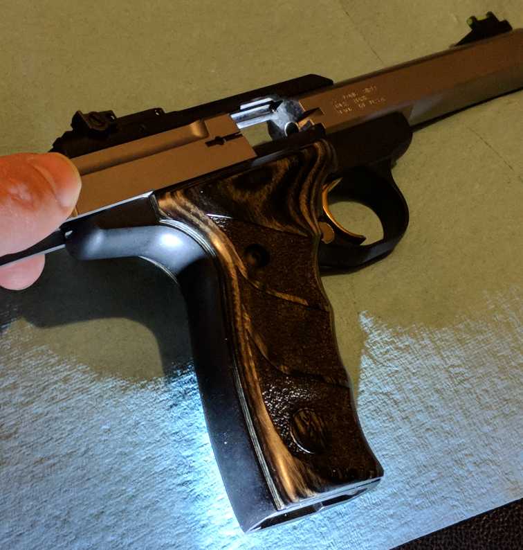
- Remove right grip (one screw) OR wrap-around one-piece grips (one screw each side, lift and slide forward)
- Remove T-shaped magazine latch spring - lift spring off the frame
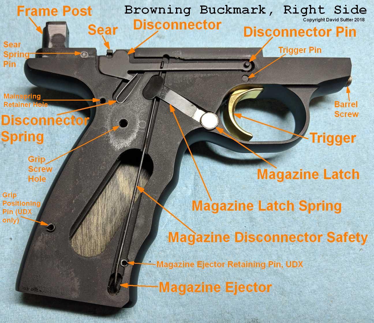
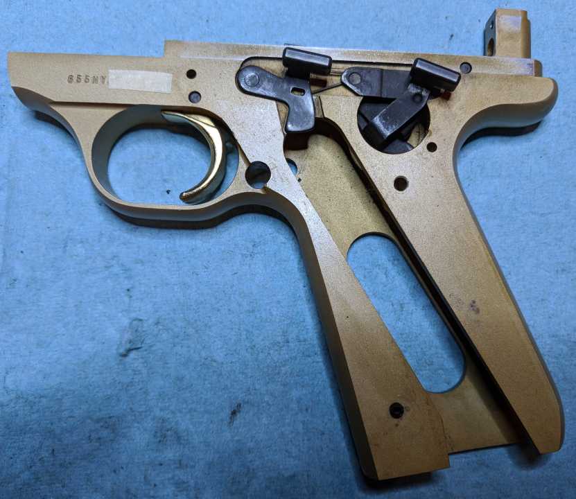
- Now is a good time to examine the Buckmark trigger mechanism
- Remove disconnector and disconnector spring - Pull disconnector off pin first, then lift disconnector and disconnector spring
- Remove magazine disconnect safety wire (on pistols made after 2005-ish) - insert magazine, angle wire up, wiggle out of magazine ejector
- Remove magazine latch - Push it from left-to-right and pull it out
- Remove left side grip (two-piece grips only) - remove screw, angle bottom up, pull from under slide stop and safety
- Remove slide stop (stop open latch assembly) - lifts straight up off the frame
- Retain mainspring - over-cock hammer, insert 1/16" hex key (or similar) all the way through both mainspring retainer holes
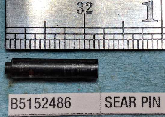
- Remove safety click plate - punch sear pin a small amount from left (1/16" punch), lift click plate off hammer pin, slide click plate out from under safety lever
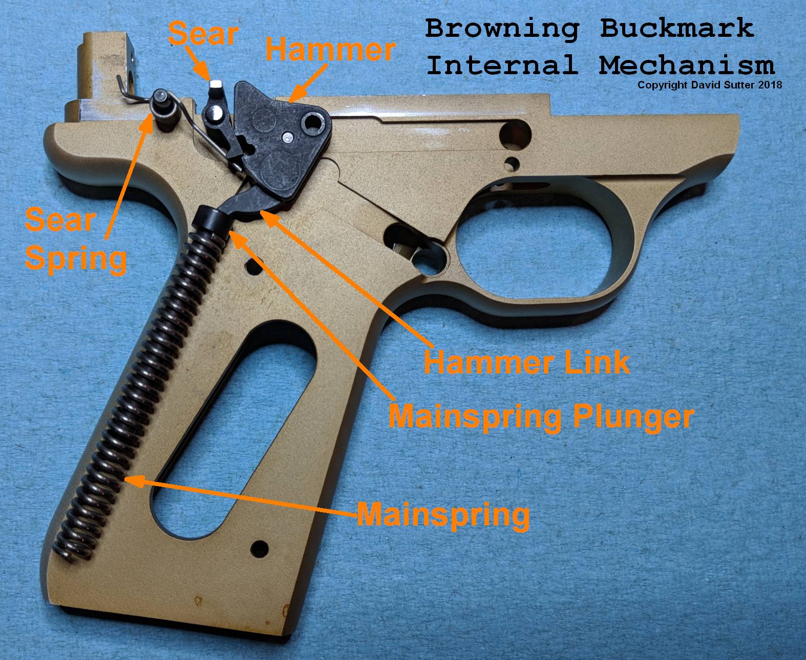
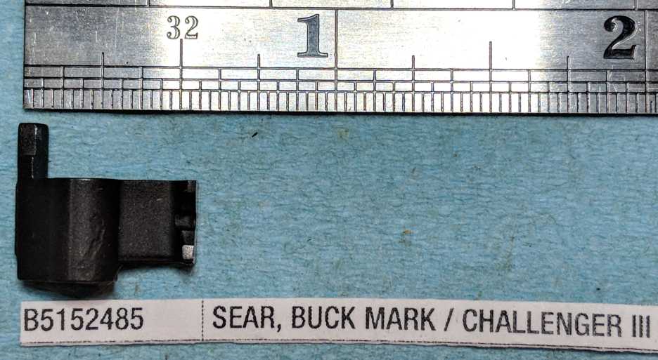
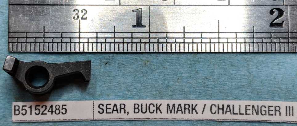
- Remove sear - Punch sear pin out the rest of the way, left-to-right (1/16" punch), pull out sear
- Remove hammer - Punch out hammer pin from right-to-left (1/8" punch), pull out hammer
- Remove safety lever assembly - rotate it counter-clockwise, angle the rear up, lift out of frame (no force required)
- Remove sear spring - punch out sear spring pin, left-to-right (3/32" punch), dump spring out of frame
- Remove mainspring and mainspring plunger - compress with large punch, remove retaining rod, slowly release the spring, dump them out
'Show/Hide Info' buttons are also available for each step to toggle showing or hiding extra info just for that step.
This page describes Buckmark disassembly only. If you are looking for resassembly steps, click here.
If you are looking for disassembly steps for a part not shown on this page, check the Sub-Assemblies page.
includes Trigger, Extractor, Firing Pin (pre-2001 or 2001-present), Recoil Spring (pre-2001 or 2001-present), Magazine, and more.
includes Trigger, Extractor, Firing Pin (pre-2001 or 2001-present), Recoil Spring (pre-2001 or 2001-present), Magazine, and more.
If you dislike these disassembly instructions, some alternatives are:
- One of the active and highly knowledgeable members of the Browning Buckmark forum on RimfireCentral.com (RFC) is Chim.
Chim's website also hosts assembly and disassembly information for the Buckmark. - Complete animated disassembly procedure of Buckmark Thread - youtube animation
- Dissecting a Buck Mark Thread on RFC
- Gun Guides makes a small, inexpensive booklet describing Buckmark disassembly and reassembly (available from Gun Guides website, MidwayUSA, Amazon) - it's ok, but the version I have does not cover all models (despite what the cover says).
How to use this web page
- In the list of steps, click on the link for each step to see the detailed description of that step. There is a link back to the list of steps at the end of each detail section.
- Directional references (front, back, top, bottom, left, right) in the instructions are always relative to the position of the part when installed in the gun.
- Click on any photo for the full-size version of that photo.
- Clicking on the "Show/Hide Info" button in the header of each section will show or hide informational details.
When hidden, only the most important text and images are shown.
This is particularly helpful when viewing the page on smaller screens, like a phone.
This is an example of informational text. Try clicking the info button in the header of this section to hide and re-show it. - Screw sizes are given as either "D-T" or "D-T x L"
(where D is diameter number, T is threads-per-inch, L is length of threaded portion in inches).
For example: 8-32 x 5/16" is a screw that is #8 diameter, has 32 threads per inch, and the threaded portion is 5/16" long. All screws on Buckmarks are in SAE units (no metric screw sizes).
- Unless otherwise noted, screw sizes and spring wire sizes were actually measured by me.
- Screw torque specifications are given here in INCH-lbs, not foot-lbs. This is a gun, not a tractor.
- If you see something wrong or missing, or know a better way, or think a better photo is needed, please let me know. I take criticism well, and want the information presented here to be the best that it can be.
What year was my Buckmark made?
Some of the steps are different for Buckmarks made before or after a certain change in parts in a certain year,
so it's worthwhile to know what year your Buckmark was manufactured. Browning has a page on
how to determine when your Buckmark was made.
But basically, look at the serial number...
If it starts with 655, it was made between 1985 - 1997
If it starts with 515, it was made between 1998 - present
Next two letters indicate last two digits of the year: Z=1 Y=2 X=3 W=4 V=5 T=6 R=7 P=8 N=9 M=0
So serial number 655NY00001 was made in 1992, and serial number 515ZT00001 was made in 2016.
Wouldn't it have been simpler to identify the gun type with three letters, and use digits for the year... like, I dunno... BMK16 for a Buckmark made in 2016?
Tools used during disassembly, cleaning, or reassembly
For disassembly and reassembly
- Hex (Allen) wrenches (these are the L-shaped metal wrenches with six flat sides)
- 1/16" hex wrench (front sight post set screw)
- 5/64" hex wrench (screw on underside of top rail that holds rear sight to the rail)
- 3/32" hex wrench (top rail screws on some models (Plus UDX), grip screws on UDX models, sear spring adjusting screw on Target & Silhouette models)
- 7/64" hex wrench (barrel screw) OR 3mm hex wrench filed down to match your barrel screw head
- 1/8" hex wrench
- 9/64" hex wrench (top rail screws on some models (Hunter))
- Pin Punches (punches with flat tips)
- 1/16" punch (sear pin, hold back mainspring during disassembly)
- 3/32" punch (sear spring pin, disconnector pin, hammer link pin)
- 1/8" punch (hammer pin, trigger pin, depress mainspring during disassembly)
- Roll Pin Punches (punches with small half-domes on their tips to center them over roll pins)
- 1/16" roll pin punch (firing pin retaining pin, rear sight windage screw detent spring)
- 3/32" roll pin punch (rear sight leaf pin)
- 1/8" roll pin punch (magazine ejector retaining pin)
- Examples of punch sets
- Bench block (to put under the gun when driving out pins).
- Small hammer (for use with the punches)
- Plastic dental pick
For pulling disconnector off the disconnector pin, general reaching, poking, and cleaning. Example: Tipton Ploymer Pick Set
- Metal dental pick
- Flat head (aka slotted) screwdriver
For grip screws (except UDX), old barrel screws, old top rail screws. If you have a flat head screw that does not come out easily, try a Chapman driver.
You can get Chapman tool sets at Amazon - Needle nose pliers
For removing the extractor, removing c-clip from recoil spring guide rod (and re-installing it), and for installing the sear spring.
- Regular pliers
For removing 2001-present slides (not needed if you have a Buckmark Maintenance Tool (BMT))
You may want to wrap the jaws in tape to avoid scratching things you use them on.
Also useful to crush q-tips so they fit in narrower spaces.
For Cleaning
- Wood stick cotton swabs (a.k.a. Q-Tips)
Cost about a penny each when bought in bulk on Amazon ( H&B brand 550, H&B brand 375, Royal brand, Amoray brand )
Pro Tip: Use pliers to crush the end of the q-tip when you need to fit a smaller space (under the extractor, in the extractor groove in the barrel, etc.)
Pro Tip: Pull 80% of the cotton off to clean inside some of the pin holes
- Toothpicks
For removing gunk from inside edges, for applying grease, and for removing the rear sight elevator detent spring.
Pro Tip: Round ones tend to be stronger and pointier, and thus preferred
- Paper towels
- Gun cleaners/solvents of your choice
Examples: CLP for parts cleaning, Hoppes #9 for bore and bad carbon fouling
For Lubricating
- Gun oil/grease/lube of your choice
Some examples:
- thin oil: Remington RemOil
- medium oil: Mil-Comm MC2500
- thick oil: Shooter's Choice FP-10
- grease: Mil-Comm TW25B
- dry lube (for magazines): Hornady Dry Lube
- action lube (for hammer/sear): Brownells Action Lube
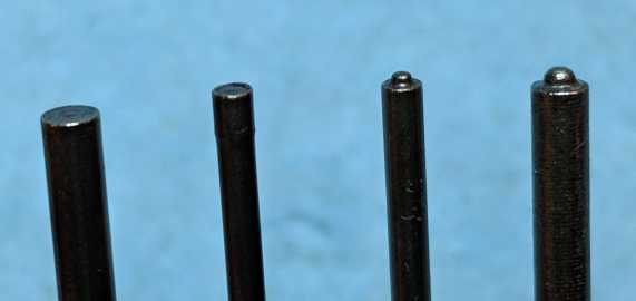
Roll pin punches on right (center half-dome)
Why your parts might look or fit different than the ones shown here
Why do my Buckmark parts look or fit different than yours?
First, although all Buckmarks share many parts, and function in a mechanically very similar way,
there have been changes, both large and small, over the years.
There have been 30+ models/variants of Buckmarks made since 1985.
Third, Browning has parts (or groups of parts) made for them in batches, and then has them assembled in model/variant-based "runs" from available parts. This leads to many minor parts changes/evolutions that can overlap in time or by variant. That is why, for many changes, it's impossible to say "after this date or serial number, all Buckmarks definitely have this new version of this part".
Fourth, certain parts are hand-fit during assembly. Most notably, some surfaces of the hammer and sear (and possibly hammer links, and pre-2001 firing pins) are essentially "custom fit" for your Buckmark. This is both good (most Buckmarks work perfectly from the factory, and require no tinkering to be functioning, reliable, accurate pistols), and bad (replacement of some parts requires knowledge, tools, and care, to get them right).
The combination of model variance, manufacturing parts tolerances, batched parts variance, and custom fitting usually explains why your parts do not look or fit exactly like my parts.
Major differences between Buckmark models include:
Second, guns are mechanical things assembled from manufactured parts.
Every part is made to certain tolerances, but when the parts are assembled,
the variability of these tolerances can accumulate, leading to what people call "tolerance stacking".
That can lead to "if your pistol has a slightly shorter part A, and also a slightly short part B,
then even though aftermarket part C fits perfectly in my Buckmark, it might not fit perfectly in your Buckmark".
- front sights (post, black ramp, fiber optic)
- rear sights (old style stamped metal, pro-target)
- sight rails (full length or half length, weaver or picatinny slots)
- barrels (4", 5.5", 7.25", 10", 14", bull, tapered/pencil, stepped, contoured, slabside)
- grip frames (standard/UFX, URX, and UDX are grip frames)
- grips (walnut, cocobolo, laminate, plastic, plastic with rubber inserts, 1-piece wrap-around rubber)
Third, Browning has parts (or groups of parts) made for them in batches, and then has them assembled in model/variant-based "runs" from available parts. This leads to many minor parts changes/evolutions that can overlap in time or by variant. That is why, for many changes, it's impossible to say "after this date or serial number, all Buckmarks definitely have this new version of this part".
Fourth, certain parts are hand-fit during assembly. Most notably, some surfaces of the hammer and sear (and possibly hammer links, and pre-2001 firing pins) are essentially "custom fit" for your Buckmark. This is both good (most Buckmarks work perfectly from the factory, and require no tinkering to be functioning, reliable, accurate pistols), and bad (replacement of some parts requires knowledge, tools, and care, to get them right).
The combination of model variance, manufacturing parts tolerances, batched parts variance, and custom fitting usually explains why your parts do not look or fit exactly like my parts.
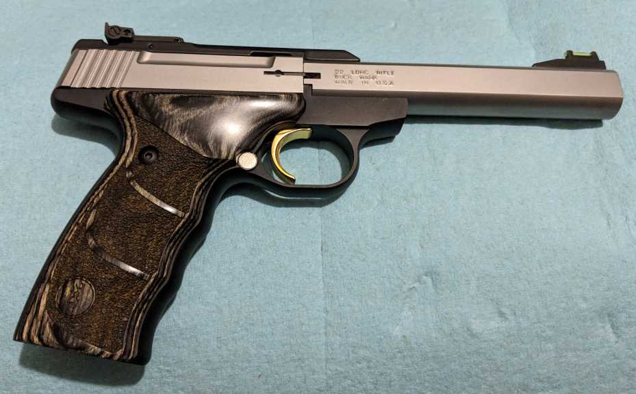
Guns used and photographed for this disassembly page
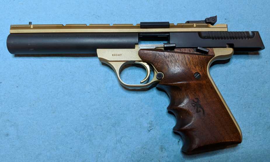 1992 Gold Target with 5.5" bull barrel wrap-around 2-piece walnut grips (standard/UFX grip frame) adjustable trigger (over-travel stop screw) adjustable sear spring (not visible here) front sight is width-adjustable post, Pro Target rear sight shown with the shell deflector installed on the sight rail The sight hoods have been removed. |
 2015 Buck Mark Plus Stainless Steel UDX Black Laminate Grips (UDX grip frame) 5.5" slab-side barrel Truglo/Marble fiber optic front sight Pro Target rear sight |
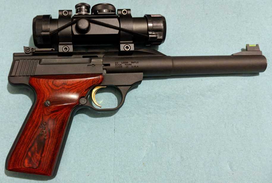 2016 Buck Mark Hunter Cocobolo grips (standard/UFX grip frame) 7.25" tapered (stepped) barrel Fiber optic front sight Pro Target rear sight UltraDot MatchDot II red dot sight |
Unload - Make sure it is unloaded
- Finger off the trigger; gun pointed in a safe direction.
- Remove the magazine.
- Rack the slide.
This should extract a chambered round (if any) from the chamber.
- Rack the slide again.
Just to make sure.
- Visually / tactilely confirm no round in chamber, and no magazine in the mag well.
Really look.THINK about what you are actually seeing (not what you expect to see).Stick your pinky finger into the mag well.Good habits.
Remove top rail and barrel together (minimizes sight change)
- Lock the slide back
This allows the feed ramp on the barrel to clear the slide when tilting the barrel off the frame
Another option is to pull the slide back with your fingers when tilting the barrel off the frame - Remove rear top rail screw (screw head may be slotted OR 3/32" hex OR 9/64" hex OR #10 Torx (T-10))
Over the years, Browning has used at least 5 different types of rail screws (two slotted, two hex, and a torx). Most are 8-36 x 1/2" long, some are 8-36 x 5/8" long.
There may, or may not, be a toothed lock washer or split washer under the head of this screw (toothed shown in photos).
A few early-90's models have a split washer under the rail, that this screw goes through.
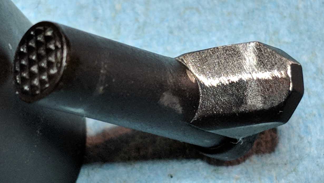
Clean any oil or grease off of this screw. It has a reputation for coming loose while shooting. - Unscrew the barrel screw about 3/8" (screw head may be slotted OR 7/64" hex OR non-standard hex OR #15 Torx (T-15))
The barrel screw is the one in front of and just above the trigger guard.
It is not necessary to unscrew the barrel screw all the way out, but it doesn't hurt anything if you do.
Recent barrel screws are 1/4-28 x 3/4" long, with a cone-shaped tip (it is not a normal screw)
Some old barrel screws (possibly pre-1992) may have had finer threads.
Over the years, Browning has used at least 4 different types of barrel screw heads (slotted, two hex, and torx). There are also nickel versions of the barrel screws on some models.
If you have a hex-head barrel screw, you may discover that it is a non-standard size.
It is nominally 7/64" hex head, and the Browning parts department will tell you they are 7/64".
Around the end of 2015, owners started complaining that the hex head is slightly larger than 7/64", but slightly smaller than 3mm, so no standard hex wrench fits it properly. Popb1949 claims in post #27 of RFC Thread 5545622 that Browning told him over the phone that this was on purpose, to prevent owners from removing the barrel.
If you have a hex head barrel screw in which a 7/64" hex wrench is loose or spins freely, try a 3mm hex wrench, it might work. But, in most cases a 3mm hex wrench will be too large (7/64" = 0.109375" 3mm = 0.11811" 1/8" = 0.125").
The solution is to file down the flats of the 3mm hex wrench until it fits tightly, but goes all the way into the screw head. File just a little on all 6 sides, not a bunch on 1 or 2 sides, and take care not to round off the corners of the hex. Use a toothpick or 1/16" hex wrench to clean debris from the screw head and to see how deep it is.
Want a dedicated 3mm wrench to modify? Bob Finger suggests McMaster Carr # 6286A16 (3mm t-handle, ball-end hex wrench)
On my 2015 Plus UDX, a 7/64" hex wrench was actually slightly too big. I actually had to file it down to fit.
NOTE: There is no anti-seize paste on the very old flat-head-screwdriver barrel screw pictured here, but newer Buckmarks come with copper anti-seize on the barrel screw (it is not thread locker). You can buy a lifetime supply of copper anti-seize paste for about $12.
HELP! My barrel screw won't come out!
Many owners complain that their barrel screw is in VERY tight, and is difficult to remove. Suggestions...
- Use a quality screwdriver or hex or torx wrench that fits tightly in the head. Cheap hex wrenches may twist or break.
- If you have a flat head barrel screw that does not come out easily, use a hollow-ground tip for a good fit.
- Try a Chapman driver. It's sort of a cross between a screwdriver and a ratchet that lets you apply a lot of torque to a screw, and comes with quality bits, like hollow-ground flat-head screwdriver bits. You can get Chapman tool sets at Amazon
- Put some penetrating oil on it (Liquid Wrench, Kroil, etc.), let it sit for a while (more than 5 min), then try again
- Insert a small punch inside the hex/torx head, and give it a couple solid whacks with a small hammer to shock the screw loose
- Use a hammer drill or impact driver to break it loose.
- If you think a previous owner has applied loctite to this screw, heat the screw (such as with a soldering iron on the screw, or by heating the wrench; do not heat the frame), and try again.
SIDE NOTE: Why is the barrel screw in so darn tight? This screw is holding the barrel to the frame, and thus it prevents the whole thing from coming apart or going out of alignment when you shoot it, and that's a pretty considerable amount of force being applied, over and over, thousands of times. It's a big, strong screw, quite possibly the largest-diameter screw on any gun that I own (certainly larger than any pin or screw on one of those fragile little 45 ACP 1911s). It's supposed to be in there tight. I'm not quite sure why people seem surprised or confused by that.
- Tilt / lift the barrel (with rail attached) off the frame


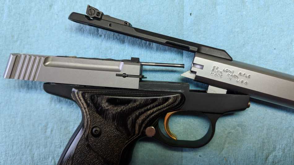
and washer (B5152699)


Remove top rail only
- Remove all rail screws (screw head may be slotted OR 3/32" hex OR 9/64" hex OR #10 Torx (T-10))
Full-length rails have 3 screws, half rails have 2 screws.Keep track of which screw came from which position.On some Buckmarks the middle and/or front screws are shorter than the rear screw. Middle and front screws may be 8-36 x 3/8" long. Rear screw may be 8-36 x 5/8" long. On the 1992 Gold Target, all 3 rail screws were 8-36 x 1/2" long. Go figure.
- Lift rail off the pistol
NOTE: You do not need to touch the sights when removing the top rail. For half-length rails, the rear sight will stay with the rail. For full-length rails, both the front and rear sights stay with the rail.
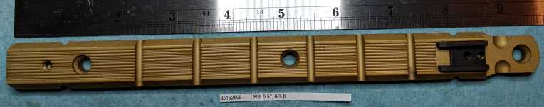

Target Rib 92-Present (B5152695)
Sight Base Lock Washer (B5152699)

Remove Recoil Spring Assembly and Slide - Pre-2001
- Hold the slide, push down the slide stop lever, and slowly let the slide go forward.
This reduces the pressure being applied by the recoil spring.
- Lift front of recoil spring assembly up, and pull the assembly out of the slide.
It may help to pull the slide back a small amount, to expose the guide rod at the frontDo not push so hard that you bend the guide rod
- Remove the buffer
The buffer may seem to be attached to the rear end of the rod. Just pull it off.
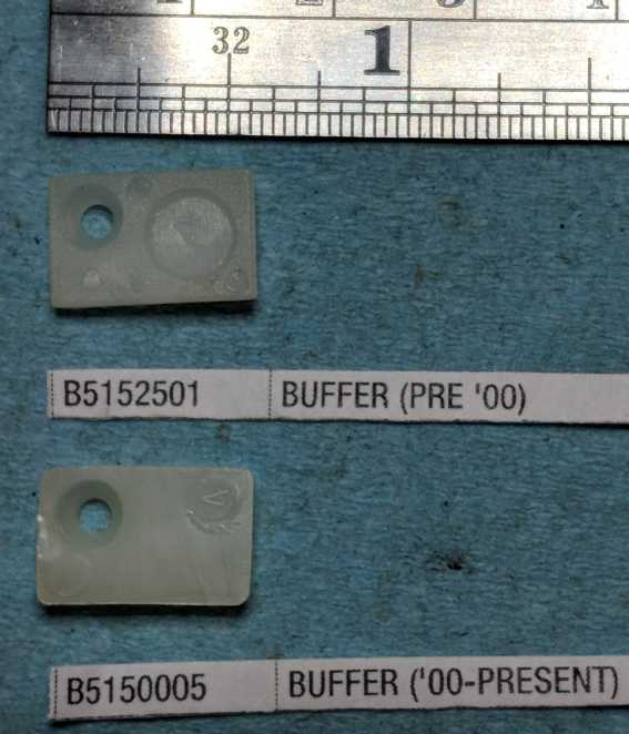
The buffer may appear to be stuck to the frame. Just pull it or pry it off.There are at least 3 different buffers:
- Black buffer - very old, no longer used, no longer available, would dry out and crumble over time
- Pre-2001 white buffer - white plastic, had raised round "lego" on the back that fit into the larger circle in the frame post.
The pre-2001 buffer is no longer made, and is hard to find. You can use the new-style white buffer instead. - 2001-present white buffer - white plastic, flat back. Still available, works on all models.
- Lift the slide off the frame (no resistance at this point)
The firing pin, firing pin spring, and firing pin retainer are all still inside the slide
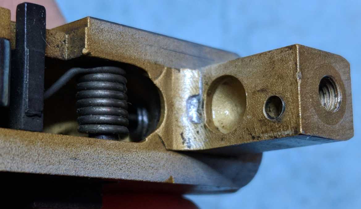
SIDE NOTE: Do I need to have a buffer? No, but really yes.
No, you don't need it, in the sense that the gun will still operate without the buffer.
Yes, you want to have a buffer, because otherwise your slide will mar the inside of your frame (see photo).
NOTE: Buffer is missing here.
(B5152684)

Pre-2001 (B5152501) and
2001-present (B5150005)
Pre-2001 and 2001-present

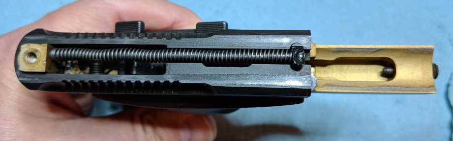
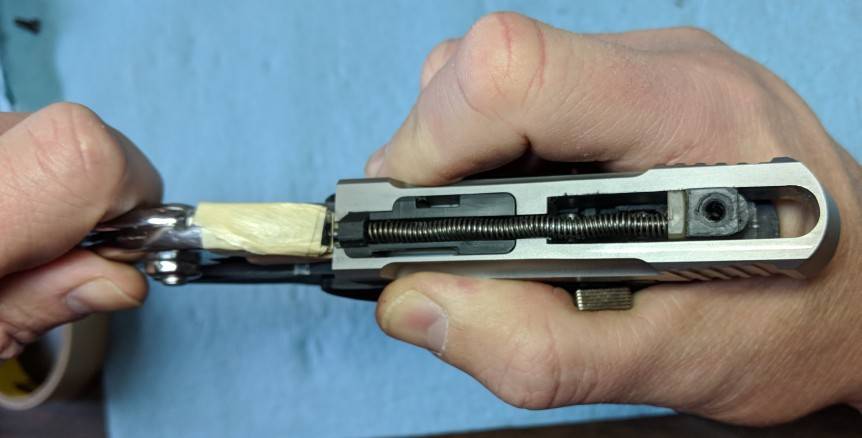
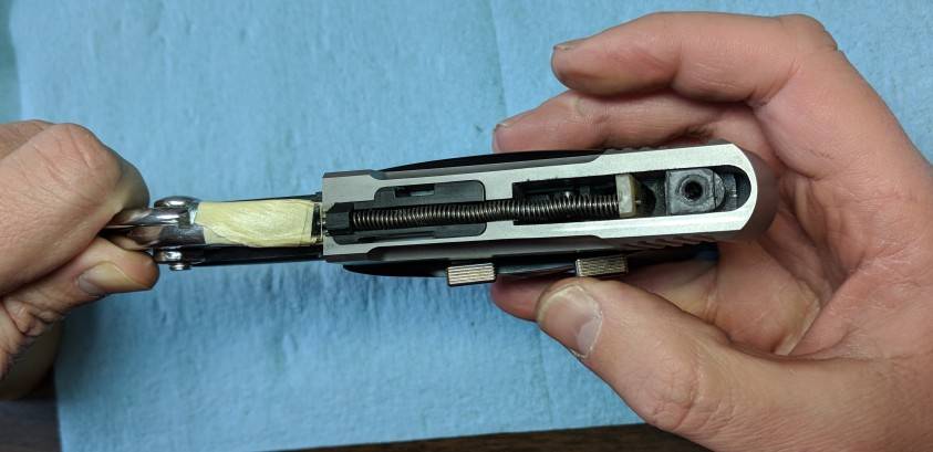
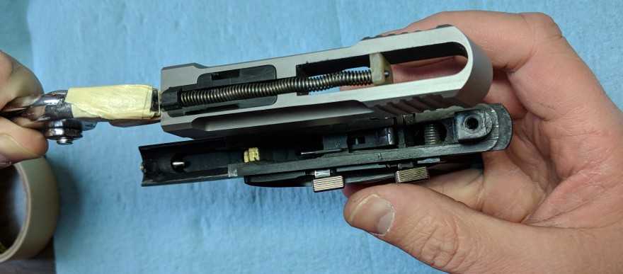
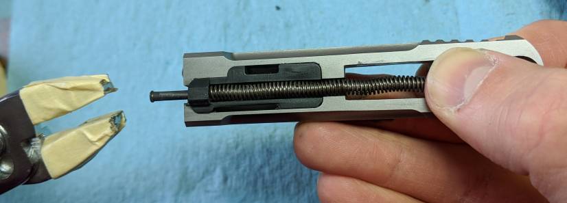
Remove Recoil Spring Assembly and Slide - 2001-present
Information
These steps include using a pair of pliers to grasp the guide rod.
Put some tape over the teeth of the pliers to avoid scratching the guide rod.
If you own a Buckmark Maintenance Tool (BMT) from Rusty22, you can use that instead of pliers.
NOTE: If you want to watch a video of this process,
watch the BMT video on Rusty22's website.
He's doing all the steps listed below, using the BMT instead of piers, and he makes it look easy.
If your buffer broke or is missing, now is a good time to get a replacement buffer ready.
Or at least get ready with something that will fit inside the slide, is thinner than the frame post,
and strong enough to hold against the recoil spring. The handle of a plastic dental pick works well.
Removal Steps
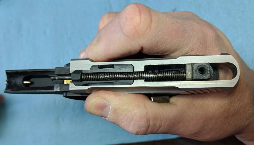
- If slide is currently held back, grasp the slide, push down the slide stop lever, and slowly let the slide go forward.
- Hold the gun upright with one hand around the grip (this is the "bottom" hand, the other is the "top" hand).
- Push slide straight back about an inch with top hand. Grasp and hold it there with bottom hand.
This exposes part of the guide rod at the front.
- Grasp exposed forward end of guide rod firmly with the pliers, being careful not to bend it.
(The only force needed is clamping force.)
If you have a Buckmark Maintenance Tool (BMT) from Rusty22, you can place that over the guide rod in place of the pliers.
- Slowly allow the slide to move forward until it stops against the pliers. Let go of the slide with your fingers.
- Move the slide+pliers unit forward about 1/4" relative to the frame,
so that the back end of the guide rod clears the frame post and/or buffer.
The buffer may stick to the guide rod, or it may stick to the frame post, or it may fall off.If the rear end of the recoil spring does not move forward with the guide rod, the tiny little c-clip that retains the spring on the back end of the rod is lost, broken, or has slipped off. Your recoil spring is going to come off in the next step. You should do the next step in a large plastic bag, or at least try to cover the back end of the spring with your hand.
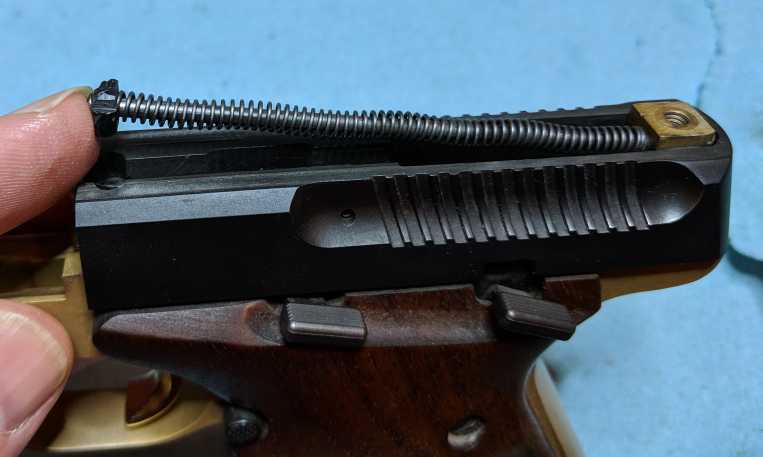
- Lift the slide+pliers unit gently off the frame. Set the frame down.
Do NOT use force. It should lift straight up and off easily.
- If the buffer is not attached to the guide rod, find it, and place the hole in the buffer over the back end of the guide rod.
Or place something else behind the guide rod.
If you cannot find the buffer, or yours broke and you don't have a replacement handy, you can use anything you have that fits inside the slide behind the guide rod, and is thinner than the frame post. The handle of a dental pick or cleaning brush, for instance. You just want to prevent the guide rod from snapping back violently when you release the pliers.
- Grasp firmly and hold the buffer (or alternative) and the slide with your bottom hand.
No movement is needed, just hold these pieces firmly, so they cannot move relative to each other.
When you release the pliers in the next step, the recoil spring is going to try to push the slide forwards and the buffer/end-of-guide-rod backwards. You're trying to prevent that from being a violent, snapping action.
- Release the pliers (or remove the BMT from the guide rod).
- Slowly allow the guide rod & buffer to move backwards relative to the slide, releasing tension on the recoil spring.
NOTE: If you just release the pliers after lifting the slide off the frame in step 8,
thereby skipping steps 9-12, it's probably not the end of the world, but I cannot recommend it.
You risk things like damaging the plastic firing pin assembly when the rod flies forward and whacks it,
or having the buffer go flying and get lost.
ALTERNATE METHOD #1
Chim's Buckmark DIsassembly website, on Page 2,
suggests a completely different method of removing the 2001-present recoil spring assembly from the frame.
His method is simpler and quicker, but requires prying that must be done carefully,
and assumes your buffer is not broken/missing. The basic steps are:
- Hold the gun upright.
- Force a knife, pick, or thin screwdriver between the frame post and the buffer.
- Gently pry the buffer away from the frame post until the tip of the guide rod clears the frame post.
- Now the slide, with guide rod assembly, can be lifted up off the frame post.
ALTERNATE METHOD #2
This method is approximately what's described in a book I have about Buckmark disassembly.
You do need to be careful not to bend the guide rod with these steps, though.
- Hold the gun upright
- Pull the slide back about an inch
- Grab the exposed end of the guide rod with your fingers
- Pull the guide rod back about 1/4" to get it out of the frame post
- Pull down on the front of the guide rod to tilt the back of the guide rod up enough to clear the frame post entirely
I'm not sure how this works unless your firing pin block is very loose in your slide, but that's what it says to do.
- Now the slide, with guide rod assembly, can be lifted up off the frame.
NOTE: Chim (a very knowledgable RFC user and Buckmark gunsmith)
has reported that he has seen some Buckmarks with the 2001-present recoil spring assembly,
where the distance between the buffer and the barrel breech face (back of the barrel)
is so tight that it is not possible to remove the recoil spring assembly without first removing the barrel.
If that is the case on your Buckmark,
see the section on removing the top rail and barrel together.
(2001-present)
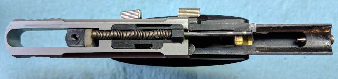
move slide forward off frame post
& slide, then release pliers
Remove right grip - OR - Remove one-piece wrap-around URX grips
Information
The one-piece wrap-around grips are typically only found on URX models
The old (early-1990s) wrap-around wood grips are two pieces that meet in the middle
in the front, even though that seam might be difficult to see.
If you have these, follow the instructions for 2-piece grips.
Removal
- For all models: Remove right grip screw (there is only one)
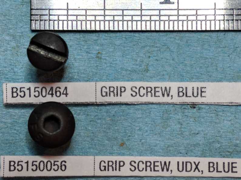
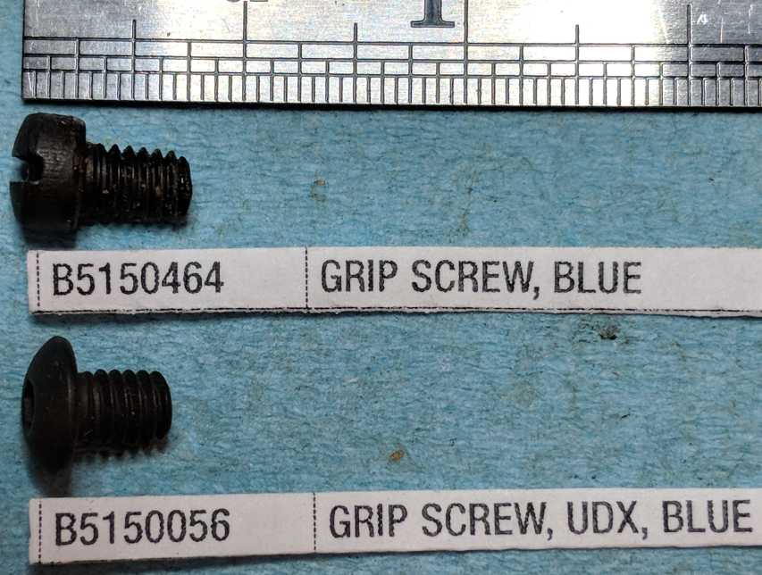
Non-UDX models use a regular flat-head screwdriver. Screw size is 8-32 x 5/16" long, head is 0.26" wide and 0.14" tall, threaded shaft is 0.225" longUDX models use a 3/32" hex wrench. Screw size is 8-32 x 5/16" long, head is 0.306" wide and 0.088" tall, threaded shaft is 0.225" longNote that, while the threaded portion is identical for both screws, the head on the hex screw is shorter and wider. The shorter head allows for thinner grips (without the screw head sticking out). The wider head means you need an enlarged countersink hole in the grip.
- For two-piece grips ONLY: Lift the right grip straight up off the frame
It is not uncommon for the grips to be a little stuck on the frame. Moderate force may be needed here.Skip steps 3 & 4 (those are only for one-piece grips).On my old gold Buckmark with split grips that meet at the front, the grips would not come off, even with moderate force. The two grip halves were stuck together in the front, possibly glued by previous owner, and needed some scary-hard prying to separate them. Please don't glue them together.
- For one-piece URX grips ONLY: Remove left grip screw (there is only one)
- For one-piece URX grips ONLY:,
Spread the grips a little on each side, and pull them forward off the frame
You only need to pull each side up about 1/4", to clear the magazine ejector pin near the bottom of the gripYou can pull one side off the pin and move it forward a little, then pull the other side off the pin, then pull the whole thing forwardNOTE: Pieces WILL fall off the frame when you do this. DON'T PANIC! Just try not to lose them.On the right side, the T-shaped magazine latch spring will almost certainly fall off.On the left side, the stop open latch assembly (a.k.a. the slide stop lever) will probably fall off.
YOU CAN HELP MAKE THESE INSTRUCTIONS BETTER: I don't actually own a Buckmark with one-piece wrap-around grips.
If you do, and have suggestions for better removal instructions for the one-piece grips, or helpful photos to contribute,
please let me know.


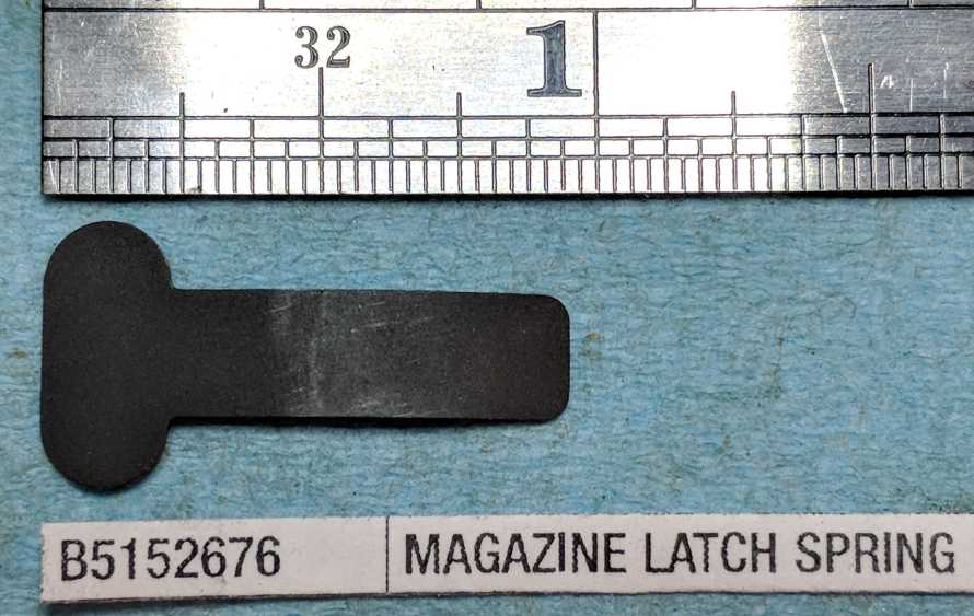
Remove magazine latch spring
- Lift the T-shaped magazine latch spring off the frame
It was only held in place by the grip.Yes, it is supposed to be curved / bowed.

Now is a good time to examine how the trigger mechanism works
Before you pull the trigger, cover the hammer with your thumb to prevent it from slamming into the frame
(it normally hits the firing pin). See photos. Put your non-firing thumb onto the top of the hammer and be ready for sudden,
significant force. Nothing horrible happens if you let the hammer whack the frame a few times,
but you shouldn't make a habit of it.
To learn more, see my page that describes the Buckmark Action
in moderate detail
Basic Steps: When you pull the trigger back, the top of the trigger moves forward,
which pulls the disconnector forward, which pulls the top of the sear forward, so the bottom of the sear moves backward,
which releases the hammer.
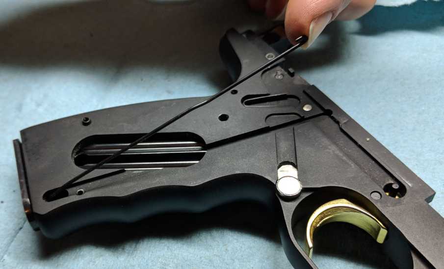
Remove disconnector and disconnector spring
- On models with magazine disconnector safety ONLY: Insert an empty magazine
This prevents the magazine disconnector safety from pulling down on the disconnector
- Cover the back of the disconnector and V-shaped disconnector spring with your thumb or finger
This prevents the disconnector spring from jumping out or flinging the disconnector
- Lift disconnector gently off the disconnector pin at the front (see photo)
I found it was easier to use a pick to lift it off of the disconnector pin first. If I lifted the back end of the disconnector first, it got bound up on the pin.
- On models with a magazine disconnector safety ONLY:
Separate the disconnector from the magazine disconnector safety wire
Pull the front of the disconnector down towards the grip, and it should come out of the hook at the top of the magazine disconnector safety wire
- Lift the disconnector off the frame
- Lift out the V-shaped disconnector spring
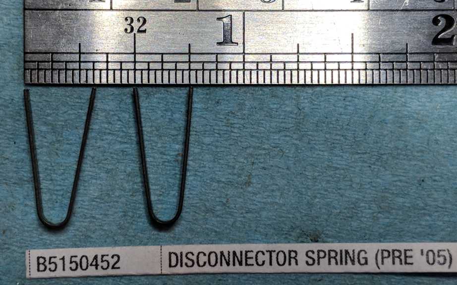
It may be helpful to push it forward and up with your finger, but it should pop out easilyThere are 2 disconnector spring part numbers: pre-2005 - B5150452, and 2005-present - B5150027. I'm not sure what the difference is, but on a new disconnector spring, the legs were about 5/16" apart, whereare on an old disconnector spring they were about 1/4" apart. Not sure if this is the difference between the new and old version of the part, or if this is just because the old spring took a set. See photo.infoinfo
OPTIONAL: Examine the wear marks on the disconnector and everything it touches...
smoothing and lubricating these friction areas will smooth out the trigger pull.
Disconnector spring is 5/8" tall, about 0.0850" - 0.0865" wide (I measured a couple different ones),
and made out of spring steel that is 0.0160" thick (pretty close to 1/64").
That rounded end fits nicely over a 7/64" rod, so, if you were making one of these, that's a good mandrel choice.
new on left
old on right
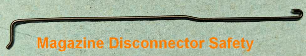
Remove magazine disconnector safety wire (if so equipped)
Prerequisites
If you're just trying to remove the magazine disconnector safety, you do not need to remove the top rail, barrel, or slide.
You just need to remove the right grip,
T-shaped magazine latch spring, and disconnector.
Information
Around 2005, Browning added a magazine disconnector safety to all Buckmark models. The purpose of this safety is to
prevent the gun from firing when no magazine is inserted. It works by pulling the disconnector down, so that the
disconnector cannot engage the sear. The wire is hooked into the magazine ejector near the bottom of the grip. When
a magazine is inserted, the magazine ejector is pushed up, which pushed the wire up, which enables the disconnector to
move up and engage the sear (the disconnector itself is pushed up by the v-shaped disconnector spring).
Why would you want the gun to be unable to fire when no magazine is inserted? Because you forgot that there is a round in
the chamber, and so it's trying to prevent a negligent discharge. If you are following the basic rules of gun safety,
this is redundant, but not everyone follows the rules.
The problem with the magazine disconnector safety is that it makes the trigger pull worse. As the trigger is pulled,
either the wire is dragging on the disconnector, or the wire moves with the disconnector and drags on the frame. Many
people report a noticably improved trigger pull with the magazine disconnector safety removed. But I'm not telling
you to remove it. That's a decision that only you can make.
Removal
- Insert a magazine
The magazine disconnector safety wire is now only anchored at the bottom of the grip frame, where it goes into the magazine ejector.
- Angle the wire up, alternately pulling up gently and adjusting the angle, until it pulls free
The bottom of the wire fits into a hole in the side of the magazine ejector. You have to work the squiggly part at the bottom of the wire out of that hole. You do not need to use force to get this piece out, it's just a matter of getting it lined up.
NOTE: I've never seen a parts list that included the magazine disconnector safety wire,
so I don't know of a part number for it.
NOTE: The magazine disconnect safety wire is size 0.0465" - 0.0475" diameter, probably 21 gauge wire
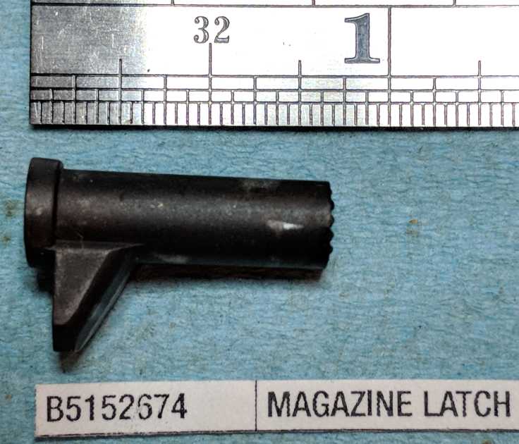
Remove magazine latch (a.k.a. magazine release button)
- Without turning the frame over, reach underneath and push and hold the magazine release button
If a magazine was inserted, the magazine should eject. The magazine latch should now stick up from the frame on the right side.
- Pull the magazine out of the gun (if previously inserted)
- Pull the magazine latch straight up out of the frame
SIDE NOTE: The magazine latch on the 1992 Gold Target appears to have been filed
to fit on the top half of the left-facing inside slanted surface (see photo)
Remove left grip (on models with two-piece grips)
- Turn the frame over, so that the left side is facing up
- Remove the left grip screw (there is only one screw)
- Lift the bottom of the grip first, then pull the grip out from under the slide stop lever and safety lever, and off the frame
In theory, no force should be required, as the grip is only held in place by that one grip screw, but in practice, the grips may be stuck onto the frame if it's been a while since they were last removed.If you bump the stop open latch assembly (a.k.a. slide stop lever) while removing the grip, and it pops off, don't panic. You just saved yourself the trouble of lifting it off in the next step. Congratulations on your efficiency.

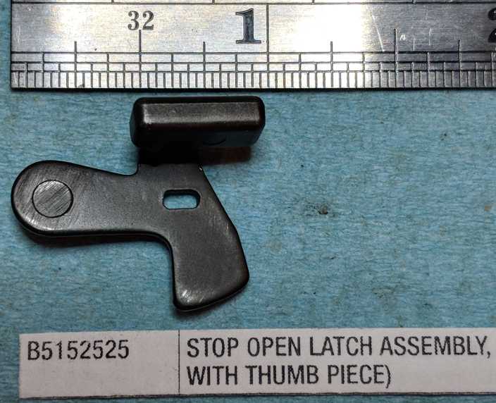
Remove slide stop lever (a. k. a. Stop Open Latch Assembly)
- Lift the slide stop lever off the frame
It was only held on by the left grip
SIDE NOTE: While you have it in your hand, check to make sure that the thumb piece is
securely attached to the rest of this assembly. Try to wiggle it. If it is not firmly attached, pull it off,
clean the old glue off both pieces, clean any oil or grease off both pieces with a solvent (like rubbing alcohol),
and reattach the thumb piece with JB Weld. It's a good, permanent fix. It's much better to take the time to
fix it properly now, than spend 15 minutes on your hands and knees searching through lead dust and shell casings on the
floor at the range, looking for the thumb piece if it falls off while you're shooting.

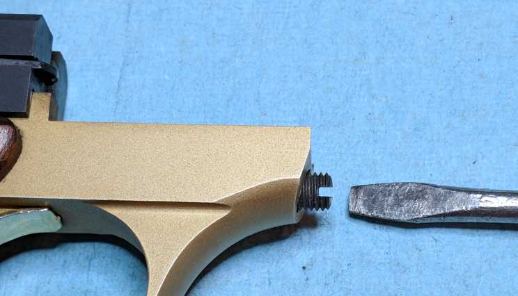
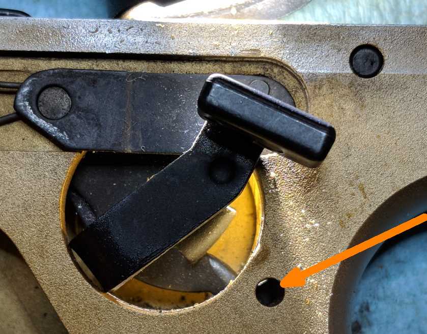
Retain the mainspring
Information
This step involves sticking a metal rod through the frame, and leaving it there for the next few steps.
The purpose of this step is to prevent the mainspring from pushing up on the hammer, allowing you to easily remove
the sear and hammer without parts going flying or getting jammed. Do not skip this step.
There are special holes in the frame on both sides, specifically for this purpose. Use them.
For the metal rod you can use a hex key, or a punch, or a nail, or a heavy duty paperclip, or bailing wire, etc.
Do not use your 1/16", 3/32", or 1/8" pin punches if you only have one punch set, because you will need them in the next few steps.
Ideally, you want to use the largest diameter piece of metal that you can fit all the way through to the other side
(which depends on your particular gun... see the note on hammer link length, below).
Don't try to use a toothpick or wooden skewer; they are not strong enough.
Removal
- Overcock the hammer. Do this by pushing the hammer down as far as you can with your thumb.
This will require some force, since you are compressing the mainspring.This should push the mainspring plunger down far enough to enable you to do the next step.
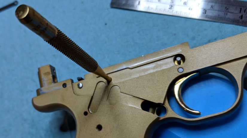
- Insert a metal rod (e.g. 1/16" hex key) into the mainspring retainer hole on the left side, over the mainspring plunger,
and through the corresponding hole on the right. Leave it there.
The mainspring retainer hole is the small, non-threaded hole just behind and below the safety lever cutout. (See photo at right.)The larger, threaded hole directly below the cutout is where the grip screw goes.Make sure you stick the metal rod all the way through, to ensure it doesn't slip out. Bad things could happen if it slipped out.
- Push the top of the sear forward to release the hammer. (It should NOT slam forward, because the mainspring is retained.)
Note that the safety lever must be in the down/off/fire position to do this.This is most important for guns that have long hammer links, as there could be some residual pressure from the mainspring on the hammer in those cases.
NOTE ON HAMMER LINK LENGTH: Your ability to insert something through the mainspring retainer hole,
over the mainspring plunger, and into the corresponding hole on the other side depends on the length of your hammer link.
If you have a very long hammer link, you won't need to overcock the hammer at all to insert the punch; the hole will be
clear already. That's annoying because then you're not removing all the pressure from the mainspring onto the hammer.
In that case, you want to use the largest punch/nail/whatever you can fit into that hole.
If you have a very short hammer link, you'll have the opposite problem... you'll overcock the hammer as much as possible,
and still not be able to insert even a 1/16" hex key or punch in there.
The 1992 Gold Target had a very short hammer link, so I had a lot of trouble with this step.
I ended up using a piece of bailing wire, but even then I had to hammer the tip of the wire flat to get it in there.
You see the tiny sliver of light in the upper left edge of the hole in the picture with the orange arrow?
Overcocking the hammer only made the gap slightly larger, so that's all the room I had to work with.
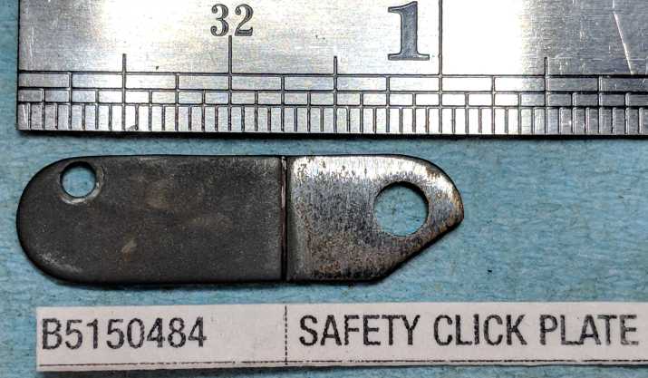
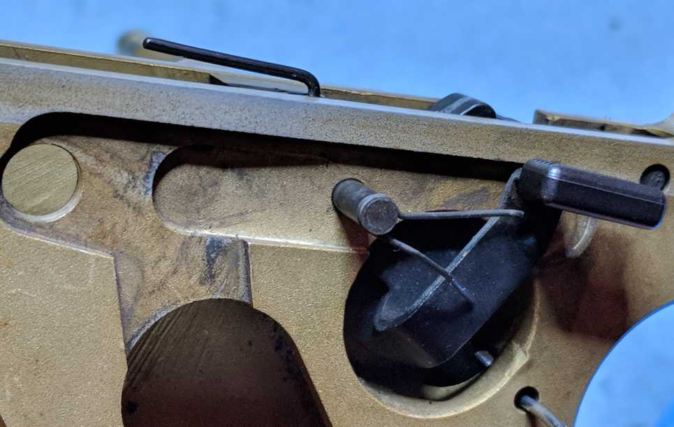
Remove safety click plate
- Push the safety lever down, if it is not already down.
- Punch the sear pin in a small amount from left-to-right (1/16" punch), enough to release the safety click plate
This MUST be done left-to-right, because the left side is reduced diameter.I've read that this pin may be peened on the left side, and staked on the right side, so this may require some force the first time you do it, so using a strong v-shaped punch (called a "solid punch") with a 1/16" tip might be the best choice.
- Pry the front end of the safety click plate up off the hammer pin
This may be easiest with a dental pick or tiny screwdriver
- Slide the safety click plate forward, out from under the safety lever, and lift it off

Left side
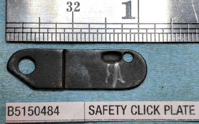
Right side
Remove Sear
- Punch the sear pin the rest of the way out (1/16" punch), left-to-right
- The sear is now loose. Remove it.
The sear may pop out (from the force from the sear spring), but shouldn't go far.If the sear falls down into the frame, you can just turn the frame over and dump it out.
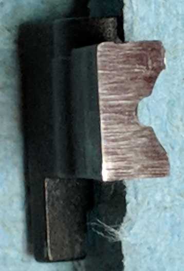
NOTE: The bottom of the sear (see photos) has been filed to fit the hammer.
In particular, examine the front bottom edge of the sear, because this is the part that holds the hammer,
and slides against the hammer when you pull the trigger. If you try to smooth this area in order to smooth or lighten the trigger pull,
be VERY gentle, you do not want to change the shape, angle, or edge geometry at all.
CLEANING NOTE: The hole in the sear can be cleaned with a q-tip that has had most of
the cotton removed.
SIDE NOTE: The wear marks along the front the of the sear are from where it rubs against the
hammer as the hammer moves up (to strike the firing pin) and then back down (as the cycling of the slide re-cocks it).
The sear is being pushed into the hammer by the sear spring.
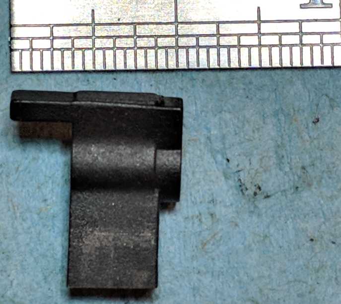
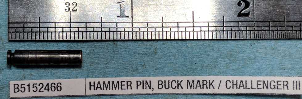
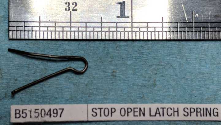
Remove hammer
- Punch the hammer pin out from right-to-left (1/8" punch)
It MUST be done right-to-left because the stop open latch spring is acting like a retaining clip on the left side. The v-shaped stop open latch spring is captive on the hammer pin, in a cannelure (groove) near the left end of the hammer pin.
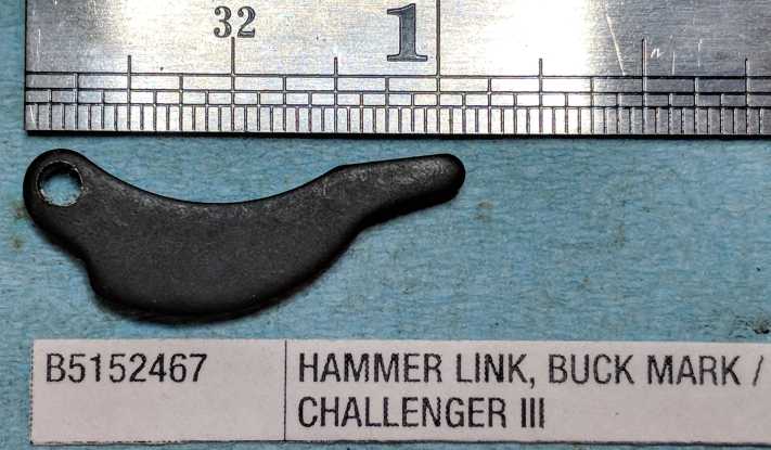
- Hammer (with hammer link and hammer link pin) is now loose in the frame, and can be pulled or dumped out
Note whether the link moves freely and smoothly inside the hammer. If not, drive the hammer link pin out (3/32" punch) to see why, and to clean and lube it. Otherwise, you can leave the hammer and hammer link connected.
OPTIONAL: You can leave the spring on the pin, or you can push the spring off easily enough.
OPTIONAL: To separate the hammer from the link, punch out the hammer link pin (3/32" punch)
CLEANING NOTE: The holes in the hammer can be cleaned with a q-tip that has had most of the cotton removed
NOTE: Stop open latch spring wire size is 0.0235" - 0.0240" diameter (probably 10 gauge music wire)
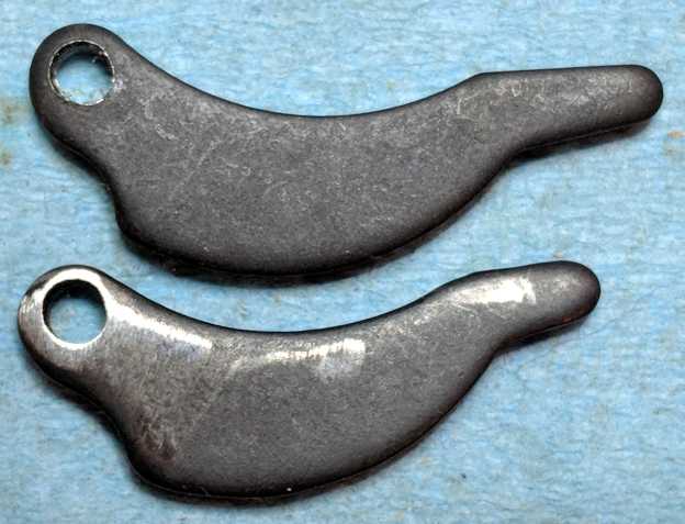
SIDE NOTE: The hammer links on different Buckmarks can vary considerably in length.
There is a good discussion of this in RFC thread 962609
posts 11-15. The hammer link on the 1992 Gold Target was very short, which is why over-cocking the hammer did not push
the mainspring down enough to fit a 1/16" hex key into the mainspring retainer hole.

Remove safety lever assembly
- The safety lever is now loose in the frame. Rotate it about 90 deg counter-clockwise, angle the rear up, and lift it out
of the frame (no force required)
On most Buckmarks you need to rotate the safety lever counter-clockwise about 90deg to align the part with the oddly-shaped hole in the frame, so that you can lift the safety lever free easily (no force is required). The 1992 Gold Target has a large round opening, so no rotating was needed; it just lifted straight up and out.

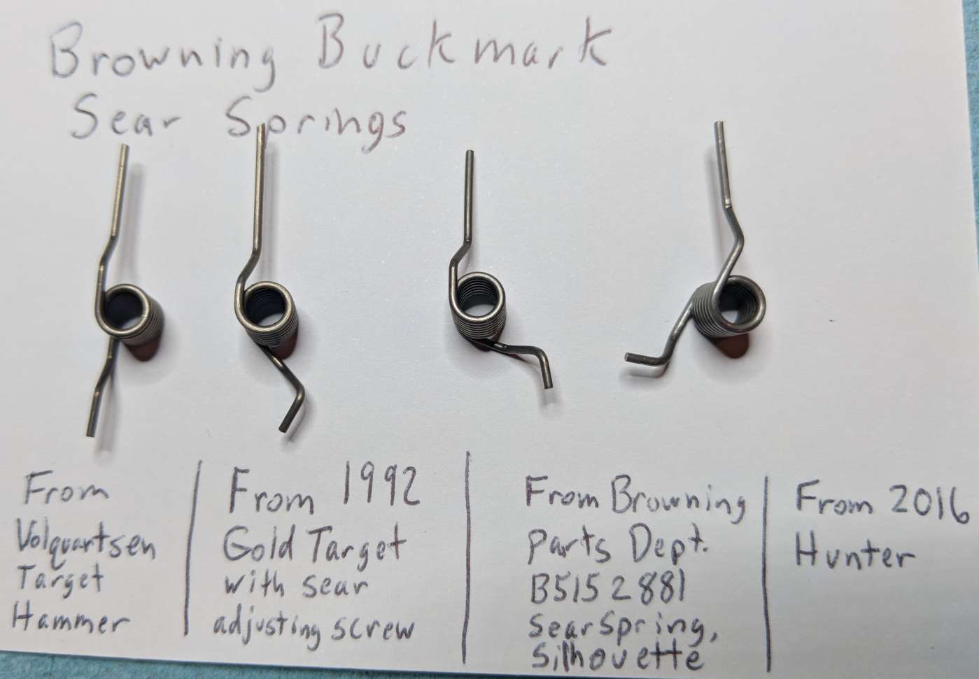
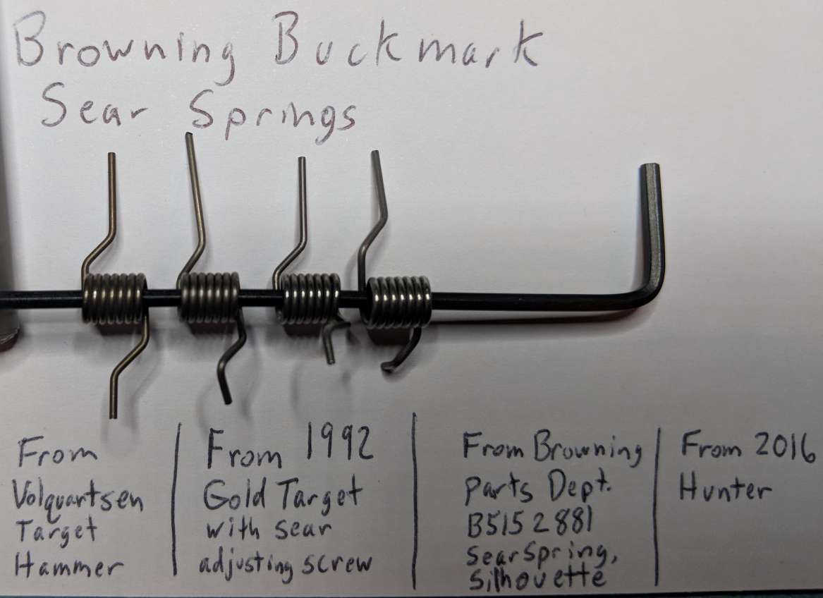
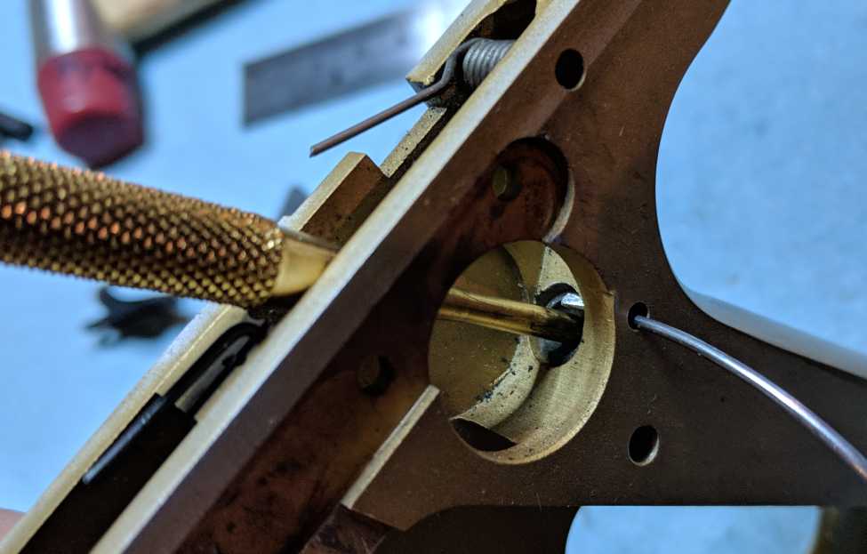
Remove the Sear Spring
- Note the location of the rear leg of the sear spring before removal
The location of this leg differs depending on the model. In most Buckmarks, the rear leg of the sear spring fits into a notch in the frame. On Buckmarks with the sear spring adjusting screw (Target and Silhouette models only), the tip of the rear leg rests inside the hollowed-out bottom end of the screw. The front leg of the sear spring goes in the V-shaped notch in the back of the sear on all models.
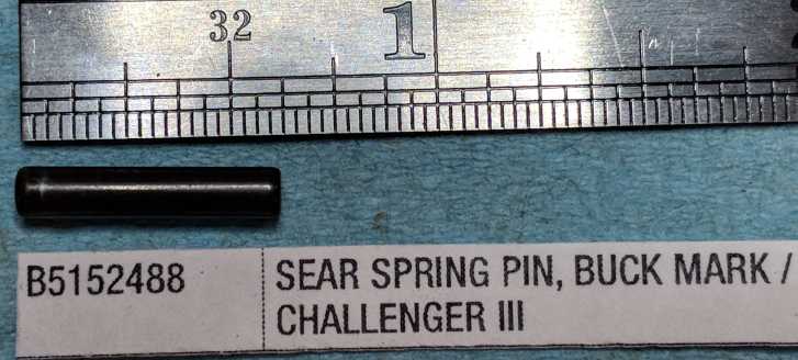
- Punch out the sear spring pin (either direction) (3/32" punch)
It should push out easily. This pin is normally held in place by the grips.
- Remove the sear spring from the frame
May require turning the frame upside down, or grabbing it with needle-nose pliers
NOTE: The sear spring pin is a plain pin, and thus easily distinguishable from the sear pin
(reduced diameter on left end), and from the hammer pin (cannelure on left end).
However, it is very similar to the trigger pin, so be careful to keep track of them if you have both of those pins
out at the same time.
NOTE: Adjustable sear spring wire size is around 0.0335", 0.0345", or 0.0350" diameter
(I measured several), probably 14 gauge (0.033") or 15 gauge (0.035") music wire.
Regular sear spring wire size is around 0.0360" - 0.0365" diameter, which is between 15 gauge (0.035") and 16 gauge
(0.037") music wire
(B5152487 & B5152881)
(various versions, all 4 sides)
Remove mainspring plunger and mainspring
Information
WARNING: This step is mildly dangerous, because the mainspring is strong. Maintain a firm grip on the larger punch.
NOTE: This step is not necessary unless you want to examine, clean, or replace the mainspring or mainspring plunger,
or you want to clean out the hole that the mainspring is in.
Removal
- Use a large punch (1/8" or so) to push down on the mainspring plunger with enough force to release pressure on the
mainspring retaining rod
The "retaining rod" is the 1/16" hex key (or similar item) that you put through the mainspring retainer holes a few steps back.
- Without releasing pressure on the larger punch, pull out the retaining rod
- Slowly allow the mainspring to push the larger punch up, until all pressure is released.
CAUTION: The mainspring is strong. (Don't shoot your eye out, kid.)The amount of movement here is small, like less than 1/2".
- Turn the frame upside down, and the mainspring and mainspring plunger should fall out.
NOTE: Mainspring is wire size 0.0500 - 0.0510" diameter, probably 23 gauge music wire.
END OF MAIN DISASSEMBLY SEQUENCE - GO TO MAIN REASSEMBLY SEQUENCE OR SUB-ASSEMBLY ITEMS