Browning Buckmark Subassemblies

If you see something wrong or missing, or know a better way, or think a better photo is needed, please contact me.
These instructions were originally written by me Nov 2017 - Mar 2018. I retain the copyright to all words and photos on this page. © David Sutter 2017-2018
Buckmark Sub-Assemblies (in alphabetical order)
Before you begin - How to use this web page What year was my Buckmark made? Tools needed and Why your parts might look or fit different- Barrel - back the barrel screw out about 3/8", and the barrel will lift / tilt off the frame
- Extractor - Removal and Installation
- Firing pin - pre-2001, 2001-present
- Magazine - disassembly, cleaning, and reassembly
- Magazine Ejector - the thing that pushed the magazine down when you press the magazine release button
- Recoil Spring Assembly - pre-2001, 2001-present
- Sear spring adjusting screw (Silhouette and Target models only)
- Sight, Front - screw-in post, pinned ramp, screwed-in ramp, fiber optic
- Sight Hoods - removal and installation
- Sight, Rear
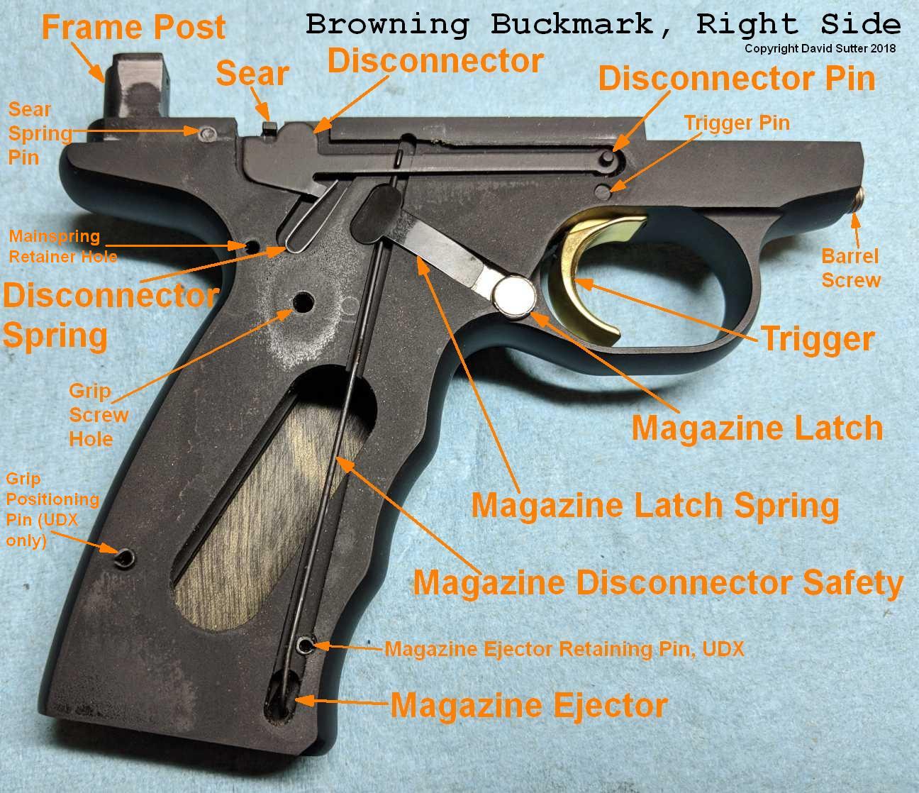
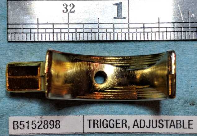
- Trigger - removal and installation
Trigger Removal and Installation
Removal Steps
- Remove right side grip (or 1-piece URX grips)
- Remove T-shaped magazine latch spring (otherwise it will fall out)
- Take photo to record how the front of the disconnector sits on the disconnector pin
- Remove disconnector
- Remove disconnector spring (otherwise it will fall out)
- Remove magazine disconnector safety wire (if equipped), just so it doesn't flop around and get in the way
- Remove magazine latch (otherwise it will fall out)
- Turn the gun over, so the left side is up
- Remove left grip
- Remove slide stop (otherwise it will fall out)
- Drive disconnector pin out left-to-right (smaller top hole above trigger) (3/32" punch)
Note that the pin itself does not go into the hole on the left side of the frame. That hole on the left side of the frame is only there to enable you to punch out this pin.
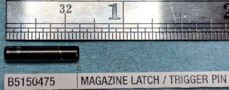
- Drive trigger pin out left-to-right (larger, longer, bottom pin above trigger) (1/8" punch)
I have no idea why this pin is called the "Magazine latch / trigger pin"... it has nothing to do with the magazine latch on this gunThis pin is 1/8" diameter and 5/8" long, which is the exact same size as the sear spring pin. As far as I know, they are interchangeable, but if you want to keep them separate, now is the time to note where you put this pin.
- Pull the trigger down and rotate the tip forward and up, to remove it.
Installation Steps
- Insert trigger into frame. Put trigger into trigger guard with the trigger facing up. Rotate it counter-clockwise to put the top of the trigger into the frame.
- Line up the lower (larger) hole. Drive trigger pin in (either direction) with a 1/8" punch.
Note that this pin is fairly loose in the frame, but fairly tight in the trigger itself. The trigger does not rotate "on" this pin when you pull the trigger, the pin rotates in the frame.Note that this pin is actually a little shorter than the frame is wide, so, when centered, this pin is actually recessed a little on both sides of the frame. This prevents the pin from rubbing against the grips, and degrading the trigger pull. The pin is 0.625" long (5/8"), and the frame is 0.652" wide.
- Drive the disconnector pin in (right-to-left) (3/32" or larger punch)
Precise left-to-right placement of this pin is importantToo far left, and it will go into the frame hole and not allow the trigger to move at all, or the disconnector will slip off of it. Test fit by slipping the disconnector on the pin, and see if the photo you took matches the depth you see.this is why you took a photograph showing how the disconnector sits on the disconnector pin... refer to it nowToo far right, and it will drag on the inside of the right grip. Test fit placing the right grip in its place and wiggling the grip forward and backward. If this causes the trigger to move at all, then the grip is touching this pin, and you need to drive this pin in farther. Further test fit by installing the right grip (tighten down the screw), and seeing if the trigger still moves freely. If the trigger does not move freely, drive this pin in farther.If you have a trigger over-travel limit screw, you can get it approximately set now. With the disconnector on the disconnector pin, pull the trigger. If the front of the disconnector contacts the frame, the trigger limit screw needs to go in farther.
- Install slide stop - place the disc on the back of it into the frame hole, and ensure that the bent-up tip of the bottom leg of the stop open latch spring is in the hole in the slide stop lever
- Install the left grip
- Turn the frame over, so the right side is facing up
- Install the magazine latch - it just drops into the frame
- Install the magazine disconnector safety wire (if equipped)- insert mag, put bottom of wire into hole in mag ejector, lay wire into frame cutout
- Install disconnector spring
- Install disconnector - hook onto magazine disconnector safety (if equipped), put tab behind spring, while pushing down slide disconnector forward, slip front end over disconnector pin
- Install magazine latch spring - lay into frame cutout, arch up, skinny end on magazine latch, wide end over magazine disconnector safety (if equipped)
- Install right grip
Notes on disconnector pin fit in trigger
If installing a new or different trigger, you may have a problem with the disconnector pin being a loose fit in the trigger.
One solution is to reduce the effective diameter of the disconnector pin hole in the trigger by peening the trigger
around the disconnector hole with a hollow punch to make the hole effectively smaller.
The process is described in RFC thread 962609, post # 24 by Nolan
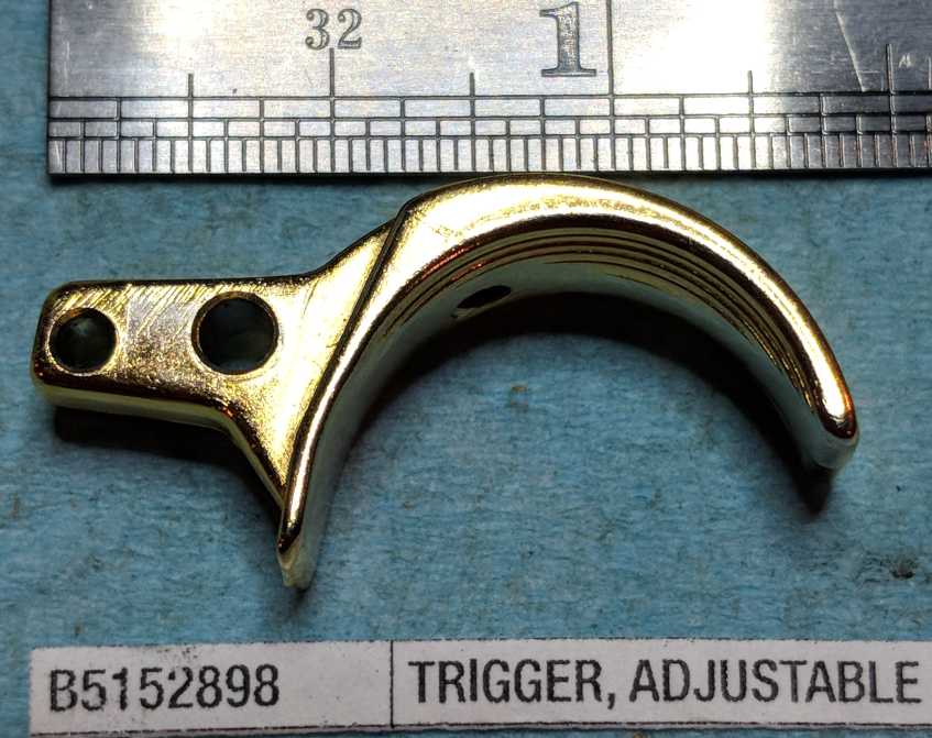
Notes on the trigger shelf
The part of the trigger that extends forward in front of the trigger pin hole is called the "shelf".
The shelf thickness controls how far forward the trigger can rotate on the trigger pin.
The trigger can only rotate until the top of this shelf contacts the frame (at the top of the trigger guard area).
Some aftermarket triggers need the top of the shelf filed down to enable the trigger to rotate enough to reset.
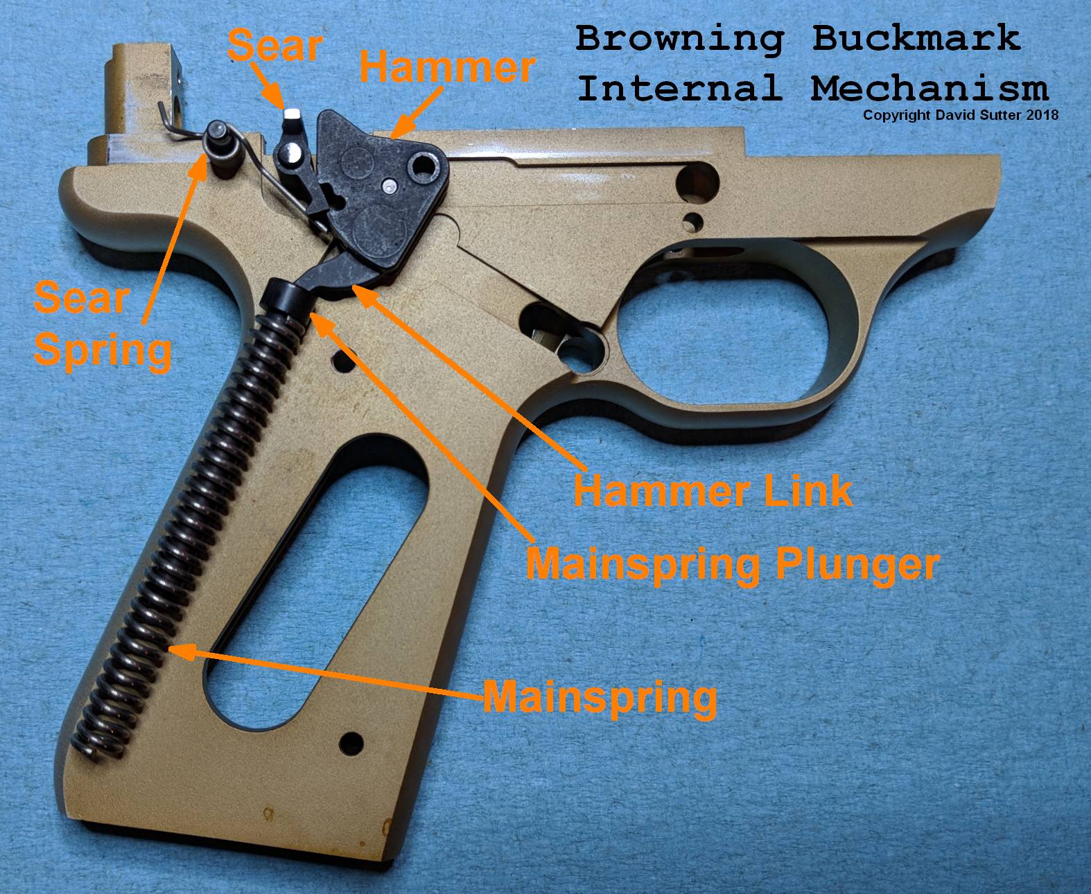
When the trigger rotates forward, it pushes the disconnector backwards, enabling the disconnector to "catch" the sear arm
(the disconnector is continuously pushed up and back by the disconnector spring).
If the disconnector cannot move far enough back to catch the sear arm, the trigger is not reset, and subsequently
pulling the trigger will not move the sear, and thus will not fire the pistol.
Conversely, adding material to the top of this shelf (such as a thin layer of JB Weld) would have the effect of reducing trigger pre-travel (by preventing the trigger from going as far forward).
Conversely, adding material to the top of this shelf (such as a thin layer of JB Weld) would have the effect of reducing trigger pre-travel (by preventing the trigger from going as far forward).
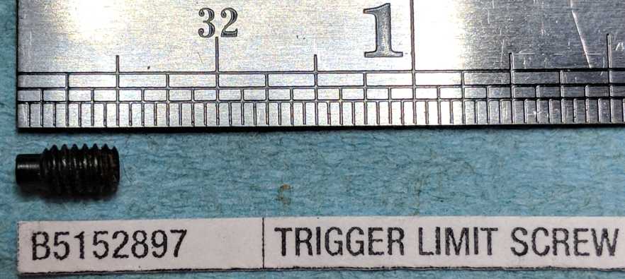
Notes on the trigger over-travel limit screw
Trigger over-travel limit screw is 5-40 x 7/32" long
The purpose of the trigger over-travel limit screw is to prevent the trigger (and your finger) from continuing to move after the trigger has been pulled back far enough to fire the gun, because any excess movement at that time leads to inaccuracy.
To adjust it, screw it in until the gun won't fire, then back it out a bit (how much???), so that the gun will fire, but the trigger has very little movement after that point. Now you have to start counting... back the screw out a few full turns, making sure you count how many you do. Then put some purple loctite 222 on the threads, and put the screw in to where you had it before. Note that, with a replacement screw, you may have to file the back of the screw (where it contacts the frame), so that the screw is adjusted correctly AND does not stick out of the trigger face (where your finger goes). Having it stick out the front is just annoying. Do NOT just file off the part of the screw that sticks out the front, because then you are removing the head of the screw, and you'll never be able to adjust it again, and you'll probably scratch up your trigger. (I know this because when I bought my 1992 Gold Target as a used gun, this is what the previous owner had done.)


Barrel Removal and Installation |
||
|---|---|---|
|
Prerequisites
If you want the barrel separated from the the top rail, you can completely remove the top rail first.
Disassembly
Then, if desired, remove the rail screws to separate the rail from the barrel
For half rails, 1 rail screw connects the rail to the barrel
For full rails, 2 rail screws (middle & front) connect the rail to the barrel
Then, if desired, remove the front sight from the barrel
Reassembly
If previously disassembled, reattach front sight and/or rail to the barrel
See instructions to Install Top Rail and Barrel Together
I've also read everything from 20 in-lbs to 50 in-lbs
Keep in mind that the frame is aluminum, so don't go crazy on it
Put copper anti-seize paste on it, so you can get it out more easily next time
|
Barrel, 5.5", Field / Target, Blue (B5152803)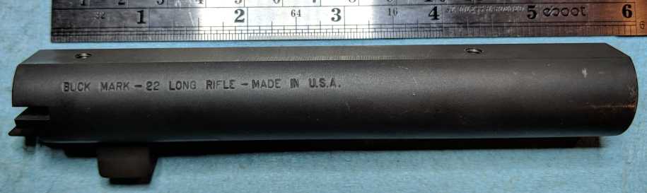 |
|
Disassembly of the Recoil Spring Assembly - Pre-2001 |
||
|---|---|---|
|
Pre-requisites
Remove top rail
Remove recoil assembly
Needle-nose pliers
Information
The "assembly" is composed of 4 parts: rod, spring, guide, and c-clip
1. Rod - 7/64" diameter and 3 7/16" long (groove is about 3/32" diameter)
2. Spring - about 4 3/4" long when free (wire size 0.0240-0.0245" probably 10 gauge music wire)
3. Guide - The guide is the black plastic tombstone-shaped piece at the front
4. C-Clip - The c-clip is a tiny c-shaped piece of metal that fits into a groove in the rod near the back, and retains the rear end of the spring
I've read that you should plan to replace the recoil spring every 5,000 - 10,000 rounds, due to wear.
I've read that the Wolff late-model Colt Woodsman recoil spring will work as a replacement recoil spring for Buckmarks.
The C-Clip is technically a "Crescent External Retaining Ring", also called "Rotor clips"
Max inside diameter is about 7/64" (0.106" measured)
Outside diameter is 5/32" (0.1545" measured)
Thickness is 1/64" (0.017" measured)
Rod diameter is about 7/64" (0.1060" measured)
Rod groove diameter is about 3/32" (~0.09375", my caliper jaws are too big to fit inside the groove)
Old factory c-clips appear to be plain steel
New factory c-clips appear to be steel with a zinc yellow coating for corrosion resistance
Closest ones I could find are 1/8" clips from G.L. Huyett, part # C-012-ZD/B
RFC User OlongJohnson found ones that he says are an even better fit. 3mm clips from G.L. Huyett, part # DC-003
See also RFC Thread 1149495 for discussion of the 3mm c-clip
Disassembly
Place assembly vertically on table with the front / guide end down and the back / c-clip end up
Pull the spring down, away from the c-clip with one hand, and hold it down (also hold the rod with those fingers)
Use needle-nose pliers to pull the c-clip off the rod
Gently release pressure on the spring
Slide the spring off the rod
Slide the guide off the rod
Reassembly
Slide the guide onto the rod, with side with the large hole facing towards the rear of the pistol
the recoil spring fits into this hole
if you install it backwards, it will bind the slide, because the notch on the bottom of the guide will not fit over the firing pin, and thus the guide will not sit down in the cutout in the slide like it should
Slide the spring onto the rod (does not matter which end of the spring is front or back)
Grab the back of the c-clip with a pair of needle nose pliers (just at the tip of the pliers)
Place the front end of the rod on the table
Compress the spring with your fingers, exposing some of the rod, and keep it compressed
Use the pliers to force the c-clip around the rod, at the groove near the rear tip of the rod
If it helps, lean the exposed part of the rod on a block and hold it there
Release pressure on the spring slowly, and put your hand over the end when you do
This keeps the spring and c-clip from flying if you didn't get the c-clip on all the way
Reassembly Alternate Method #1
In RFC Thread 1149495 user OlongJonhson suggests an easier method
Slide the plastic guide and spring onto the rod as described above.
Pull the spring down
Place the rod in a vise with non-marring jaws (plastic, leather, etc.), so that the groove is level with the top of the vise
Lay the c-clip on the top of the vice jaws
Use a flat-bladed screwdriver to push the c-clip onto the rod
The big advantages here are that the vise holds the rod solidly, and the vise also holds the spring down. That allows you to slide the c-clip on with minimal drama.
|
Recoil Spring Guide Assembly (B5152684) C-clip removal 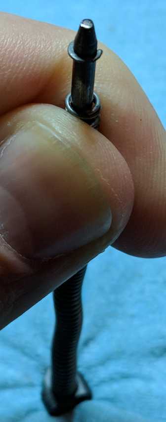 C-clip (B5152681) (old, new from factory, 3/32" E-clip)  Recoil spring guide rod (B5152683) 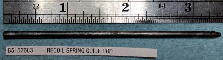 Recoil spring (B5150481) old above, new below (showing spring age set-in) 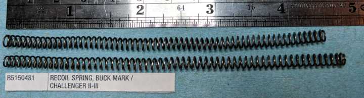 Recoil Spring Guide (B5152682) (rear end facing up) 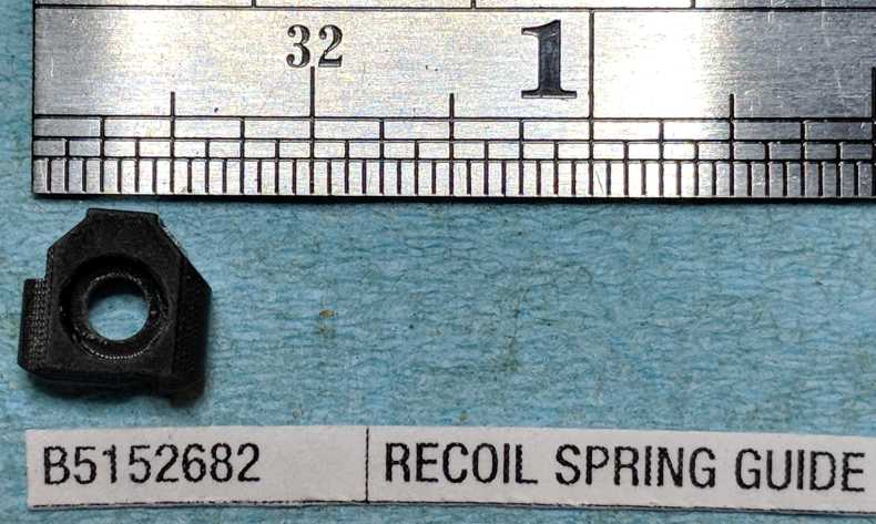 |
|
Extractor - Removal and Installation |
||
|---|---|---|
|
Pre-requisites
No preparatory disassembly is necessary. Can be done on whole pistol. Might be easier if you remove the slide first, though.
Metal dental pick with an angled tip - This is very, very helpful here. The delrin / plastic ones are not strong enough.
Needle-nose pliers
Information
Note that the tip of the extractor should be sharp, but the edge is not flat / square. The bottom of the edge should be rounded.
The main reason for replacing the extractor is because the tip of the claw chipped or the entire extractor has gone missing.
Aftermarket extractors are available from ???
Sometimes people replace their extractor thinking it will help with the problem where the shell casing is not removed from the chamber after firing.
Remember, however, that the Buckmark operates on the blowback principle, so it's really the force of the expanding gasses from the primer & powder that push the shell casing out of the chamber (with so much force that the shell casing pushes the slide hard enough to cycle the slide). If the shell casing is not leaving the chamber, it is more likely due to a dirty chamber, or a chamber that has been so badly peened by a too-long firing pin that it is preventing the case from leaving reliably. Check those things before replacing your extractor. So what's the purpose of the exatractor then? To hold / control the shell casing until ejection, to allow manual extraction (when unloading the gun by racking the slide), and to provide a pivot point for ejection.
Removal of extractor, extractor plunger, and extractor plunger spring
Lay the gun or slide with the right side facing up
Force the tip of the metal dental pick between the extractor and the plunger
the plunger is held against the extractor by a spring, so the plunger should move backwards
Pull plunger back with pick, far enough to expose the entire extractor
Grab the front of the extractor with the needle-nose pliers and lift the extractor straight up and out
Do not let go of the plunger with the pick yet
Cover the opening at the front of the slide with your finger, THEN carefully move the pick towards the opening, releasing pressure on the spring
otherwise, the plunger will go flying, fast & far (and it's tiny, so it's easy to lose)
If the spring does not simply fall out when you tip the slide, use the pick to gently pull the spring from the slide
Reassembly of the extractor, extractor plunger, and extractor plunger spring
Hold the slide or gun with the front up
Drop the extractor plunger spring into the extractor groove
Hold the plunger so that the flat part faces the inside of the slide (left side of the gun / slide)
Drop the plunger into the extractor groove
Now place slide or gun on the table with right side facing up
Hold the extractor in one hand so that the rounded end faces forward, and the tip of the claw faces the inside of the slide (currently down towards the table)
Put a finger from the other hand over the extractor groove
Push the extractor into the extractor groove, and also push down with the finger covering the groove
The extractor will snap into place
Test movement of the extractor... it should be easily moved away from the chamber, and the spring should snap it back into place (see photo)
|
Front of the extractor, showing the shape of the claw tip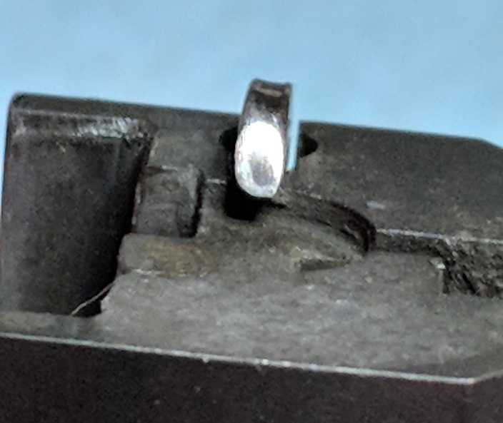 Push tip of pick between extractor and plunger 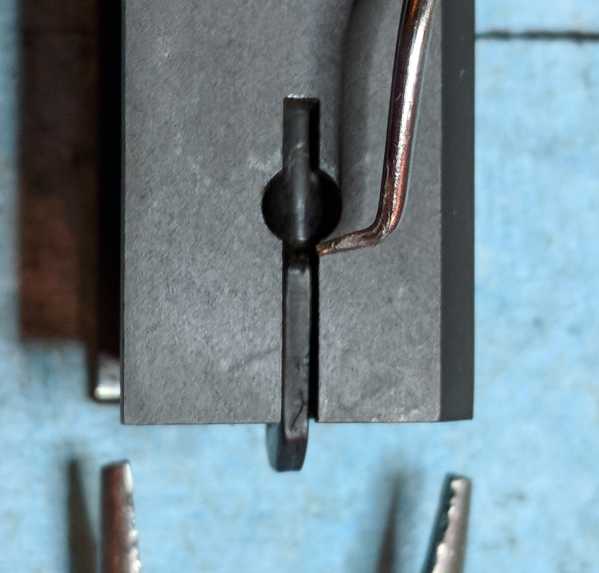 Pull back the plunger to expose the extractor 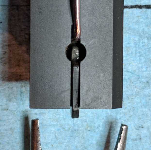 Extractor pieces  |
Extractor (B5150454)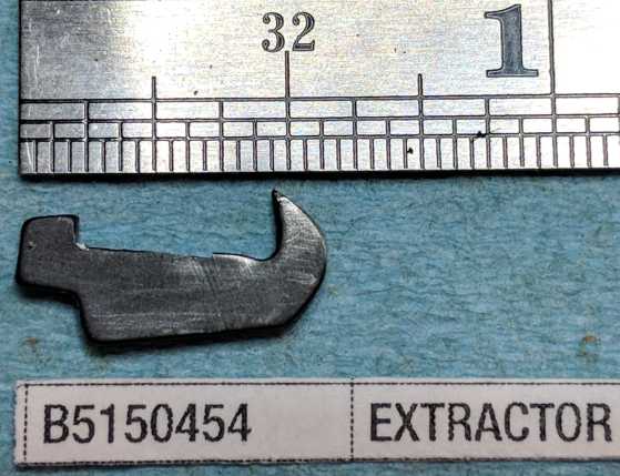 Extractor Plunger (B5150455 - "Extractor Spring Models"?)  Extractor Spring (B5150456)  Extractor movement  |
Firing Pin (pre-2001)
Prerequisites
Information
Spring seemed to be ok
Back of firing pin is mashed a bit
maybe from no buffer
maybe from use (gets hit by the hammer)
may be causing the light strikes, because this has made the firing pin about 0.5mm shorter
Removal of pre-2001 firing pin
- Step1
- Step2
- Step3
Step3 info
- Step4
Drive out firing pin retaining pin (either way seems fine) (1/16" roll pin punch)
be careful when removing the punch, as the firing pin spring is pushing on the firing pin
Firing pin just lifts out
Firing pin spring was at a strange position, looked to be jammed in there, bent upwards
NOTE: Old firing pin retainer (B5152658) is a roll pin that is about 9/16" long
The new firing pin retainer pin (B5150004) is a solid pin that is about 1/2" long (a little shorter)
old firing pin spring wire is 0.0130" diameter, probably 4 gauge music wire
Installation of pre-2001 firing pin
- Punch the firing pin retainer roll pin into the slide a small amount to get it started, but not so much that it protrudes into the firing pin slot (or else you won't be able to put the firing pin into place).
It helps to have a roll pin starter punch (hollow tip that goes around the roll pin) for this
- Place the slide in a vise, top up, so that it cannot move side-to-side
if you don't have a vice, maybe put the slide on the table and put a thin, heavy object, such as a board, on the table next to the slide, to resist the sideways movement of the slide when you start hammering on that roll pin again in a minuteIf using a vice, I recommend using some magnetic soft rubber vice jaws to prevent scratching the slide.
- place front of the firing pin spring into the slide cutout
- place firing pin on top of spring and push it forward and down until it's in the slot, with the spring underneath the firing pin
- take a small punch (1/16"?) and put it through the other side of the slide
- push the firing pin forward so that the hole in the firing pin body is lined up with the small punch, and push the small punch in further, so that it holds the firing pin in the forward position
the purpose of this punch is to align the hole in the firing pin body with the retainer roll pin, which is otherwise difficult, because the firing pin spring is constantly trying to push the firing pin backwards. This punch also holds the firing pin in place in the slide, so that it doesn't pop up and go flying.
- while holding the small punch in place, gently tap the firing pin retainer roll pin with a small hammer, pushing the small punch out, as it goes in

Reinstallation of firing pin pre-2001
Removal of firing pin 2001-present
NOT DONE YET
The new firing pin retainer pin (B5150004) is a solid pin that is about 1/2" long (a little shorter)
Magazine Ejector |
||
|---|---|---|
|
Removal
These steps will remove the magazine ejector, magazine ejector spring, and magazine ejector retaining pin (B5150514 aka 'grip pin' in Brownells schematic)
Drive magazine ejector retaining pin out (1/8" roll pin punch)
When removing the punch from the frame after the pin is out, hold your finger over the magazine ejector, so that it does not go flying
Pull magazine ejector out
Tilt frame and the spring should fall out
NOTE: Magazine ejector & spring are different for the "Challenge" frame (Challenge parts: mag ejector B5152617, spring B5152618)
NOTE: Magazine ejector retaining pin is different for UDX models (UDX part # B5150055)
Magazine ejector spring wire size is 0.0260" diameter, probably 11 gauge music wire
Cleaning
It shouldn't be too bad, but you can clean out the hole in the frame with a q-tip
Installation
Using a 1/8" roll pin starter punch that fits over the magazine ejector retaining pin, hammer the pin enough to get it started, but not so much that it protrudes into the magazine ejector hole in the frame
Turn the frame upside down, and drop the spring into the hole in the frame
Drop the magazine ejector into the hole, flat end first (round end out), with the cut out in the body facing the back of the frame
While pushing the magazine ejector into the frame with your finger, hammer the pin in, at least until it holds the magazine ejector
Placing the frame on the bench block with the magazine ejector retaining pin hole over a hole in the bench block, use a 1/8" roll pin punch to hammer the pin in until sticks out an equal amount on both sides of the frame
Ensure that the magazine ejector can be pushed in with your finger, and is pushed back out again by the spring
|
Add photo Magazine Ejector Add photo Magazine Ejector Spring Add photo Magazine Ejector Retaining Pin Add photo of removal Add photo of installation |
|
Sight Hoods
Information
The purpose of the sight hoods is to shield the sights from glare, making it easier to use the sights in bright sunlight or strange indoor lighting.
They are just bent pieces of springy steel painted black. However, they have been discontinued for several years. Since they are such a striking visual element, they have become highly coveted. How highly? Apparently people have paid over $125 for a set of sight hoods!
Removal
They can be slid off the rail, or they can be spread apart and lifted off the rail.
Difficult to remove without scratching the rail sides
Snap-ring pliers (that open when squeezed) can be helpful to spread the hood from the inside.
Front Sight - Removal and Installation
Information
There are at least 3 different types of Buckmark front sights (not counting fiber-optic vs plain black metal):
- Ramp/Blade, Screwed on - the front sight blade sits on a base that screws directly into the barrel. This style comes in both plain metal painted black and fiber-optic. Some models (micro, others?) also have a pin that sticks out the bottom of base and into a corresponding hole in the top of the barrel.
- Post - a width-adjustable post that screws directly into the top rail (Target and Silhouette models). It is held in place by a set screw (1/16" hex) that is accessible from the front (small hole in the top rail, just above the muzzle).
- Ramp/Blade, Pinned on - the front sight blade extends down into a slot in the top rail, and is held in place by a pin that goes left-right through the top rail and through a hole in the recessed portion of the blade. Seen on Countour models.
Removal of Post-style front sight
- Back out the front sight retaining (set) screw a couple of turns
Front sight post retaining (set) screw is 1/16" hex screw (screw size is 5-40 x ???" long)
- Unscrew the front sight post
Front sight post is screw size 10-32
Removal of Screw-in ramp-style front sight
- Remove the screw, and the front sight will lift (or fall) right off
Uses a 5-40 x 3/8" long screw
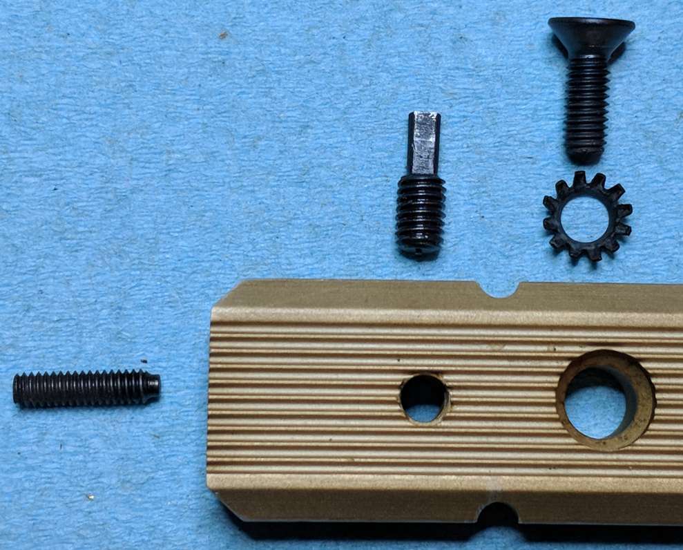
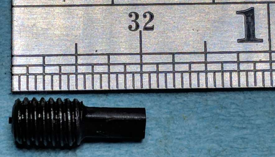
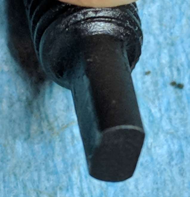
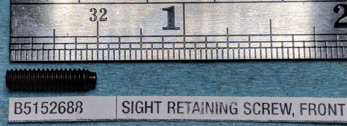
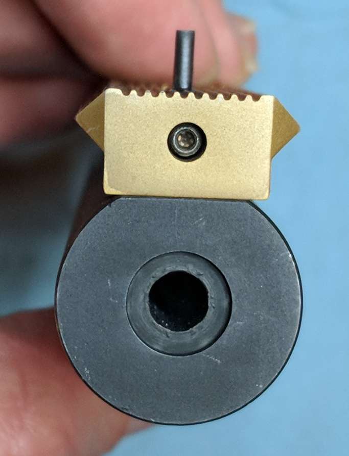

Photo of Front post sight wrench
Rear Sight
Information
- RFC Thread 385714 has excellent photos, descriptions, and part numbers for the plastic and metal rear sights.
- One common reason for removal and reinstallation of the rear sight, is because for a while some Camper models came with a plastic top rail that incorporated the sight mounting bracket (the rail and bracket were one piece). There were issues with these plastic rails cracking, and the recommended fix was to replace the plastic part with their metal equivalents.
- Another common reason for removal and re-installation of the rear sight, is because you want to install the Williams Fire Sight fiber-optic rear sight sold by Williams Gun Sight. Williams has some cursory installation instructions here.
- Regarding the rear sight blade: From Nolan in RFC Thread 4475343, particularly post #11 in that thread, the difference between the standard rear sight blade (B5152843) and the target rear sight blade (B5152841) is that the target model has a narrower-width notch. Per WildBill in RFC Thread 1207371 the standard rear sight blade (B5152843) notch is 0.125" wide, and the target rear sight blade (B5152841) notch is 0.70" wide.
Removal
- Remove roll pin going across the front of the sight (with 3/32" roll pin punch) (Sight leaf pin B5152850)
- Unscrew the Sight Elevator Screw (B5152846) (a.k.a. elevation screw) completely, and remove it. Sight Elevator Screw size is 5-44
- The Sight Leaf is now loose, and can be pulled up off of the sight mounting base.
- Remove the 3-pronged Sight Leaf Spring (B5152851).
- Turn the sight leaf over.
- Remove sight elevator detent spring (B5152845). Stick a toothpick into the front of the spring, and it will pop up onto the toothpick. pull it out
- Push out the tiny sight elevator screw detent pin (B5152848) that goes sideways across the sight leaf. I used a small paper clip (both 1/16" punch and 18ga wire is too big). It pushed out easily.
- Sight elevator screw detent (B5152847) is now loose (mine just fell out).
- Push out roll pin that is just in front of windage screw (1/16" roll pin punch). I think this is Sight Windage Screw Detent Spring (B5152854). I punched it out right-to-left, but, in retrospect, it might be better to do it left-to-right.
- Remove retaining ring (B5152855). (I did not actually do this step, but perhaps try using the tip of a knife blade to pry it up?)
- Push/punch the windage screw (B5152852) out from left-to-right
- Rear sight blade (B5152841) should pull out the top
- Rear sight blade spring (B5152844) should pull out of the hole in the sight blade.
- The T-shaped part that's left is the Sight Leaf (B5152849)
- If (and only if) you want/need to remove the sight mounting bracket (not usually necessary), there are two different types.
- Screwed in from the bottom (part ???).
If you have not already done so, remove the top rail from the frame. Remove the screw on the bottom of the top rail (5/64" hex wrench, screw size is 5-44, part B5152680 SIGHT RETAINING SCREW, PRO-TARGET). The base will still be tightly held by the top rail. I'm not sure what the best way to remove it from the rail is, but more or less you need to pry it up off the rail.
- Pinned to the top rail (B5152842 SIGHT BASE, PRO-TARGET).
There is a pin going across the top rail that holds the sight mounting bracket in place (B5152685 SIGHT BASE PIN, CAMPER / STANDARD / PLUS (DISCONTINUED)). Drive out that pin (punch size ???), and then the mounting bracket can be removed from the top rail.Link to Brownell's Page for B5152842 (has photo)
- Screwed in from the bottom (part ???).
Reassembly and Installation
- Insert the sight blade spring (B5152844) into the the hole in the sight blade (B5152843).
- Drop the sight blade into the sight leaf (B5152849). Make sure the narrow part is towards the rear (arrow inscribed inside the notch points forward).
- Holding the blade in place, turn the sight leaf upside down.
- Push the windage screw into the leaf, going through the spring (which is inside the sight blade).
- Push retaining ring (B5152855) onto the shaft of the windage screw (on the side closer to the head of the windage screw).
- Punch the Sight Windage Screw Detent Spring (roll pin) in from right-to-left, otherwise it hits the detent, preventing it from going all the way in.
- Lay the leaf down, upside down.
- Lay the elevator detent in the track (pointy end towards the rear) such that it is lined up with the pin hole
- Insert the tiny sight elevator screw detent pin (B5152848), capturing the detent. This is very easy to do with your fingers.
- Place one end of the sight elevator detent spring (B5152845) into the track at the front of the sight
- Place your finger over the spring (ready to push down on the spring)
- Use a small screwdriver to push the rear end of the spring backwards
- When it clears the back of the detent, push it down with your finger
- If you removed the sight mounting bracket from the top rail, reinstall it now. Place it in the rail, and attach it with the screw or cross pin (depending on model).
- Place the Sight Leaf Spring (B5152851) inside the sight mounting bracket, with the fingers towards the rear, the middle finger bent down, and the two outer fingers bent up. The front should be even with front of the inner part of the sight mounting bracket.
- Place the sight leaf over the spring, so that it is lined up with the holes in the mounting bracket.
- Punch the Sight Leaf Pin (B5152850) roll pin through the mounting bracket and sight leaf (with 3/32" roll pin punch), until it is flush on both sides. Note that you can start this pin with a roll pin starter punch, but don't go too far with it, otherwise you'll mar the rail just below this pin (guess how I know this?)
- Make sure that the Sight Leaf Spring didn't move out of place while driving the Sight Leaf Pin in place. You may need to push it forward into place with a small screwdriver.
- Screw the Sight Elevator Screw (B5152846) into place. After a revolution or two, it should engage the sight elevator detent, and it should click with each 16th of a turn (this should make it a little harder to turn the screw, but it should still turn fairly easily). If it is not clicking, it suggests an issue with the installation of the elevator detent or its spring.
- Test the installation by turning the elevation screw. The sight leaf should move up and down, and be held firmly in place at any setting. If it will not stay up at the higher settings, you may need to replace the sight leaf spring.
- Test the installation by turning the windage screw. It should click with each 16th of a turn, and the blade should move left-and-right within the leaf as you turn the windage screw. The blade should be held firmly in place at any setting. If not, you may need to replace the windage spring.
Add link to photo of windage screw (B5152852)
Add link to photo of sight blade (B5152841)
Add link to photo of sight blade spring (B5152844)
Add link to photo of Sight Leaf (B5152849)
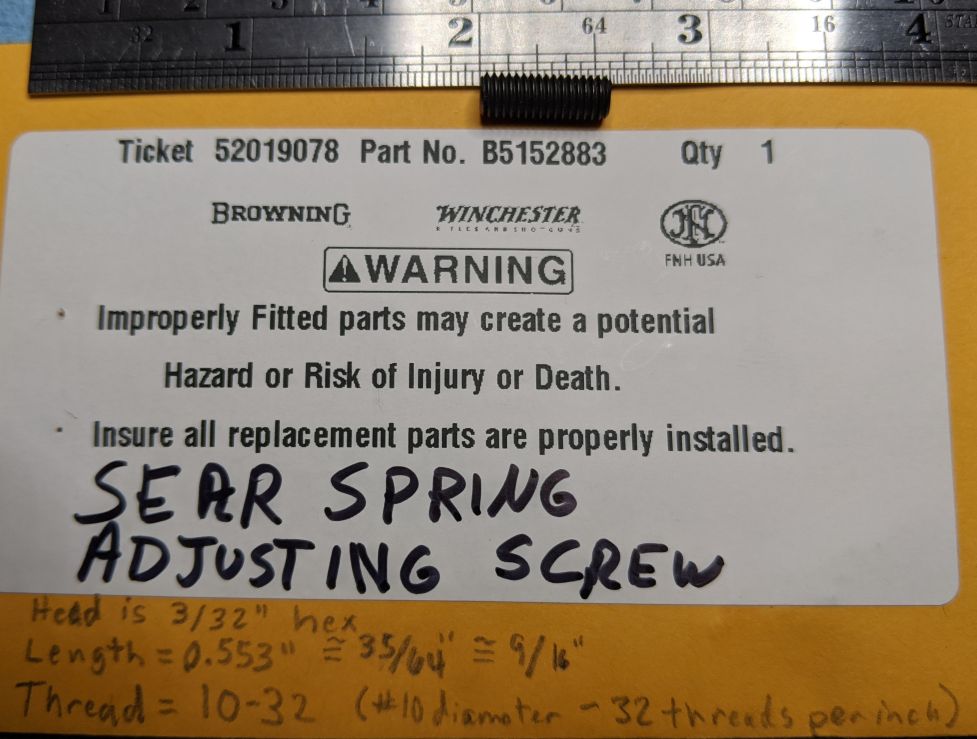
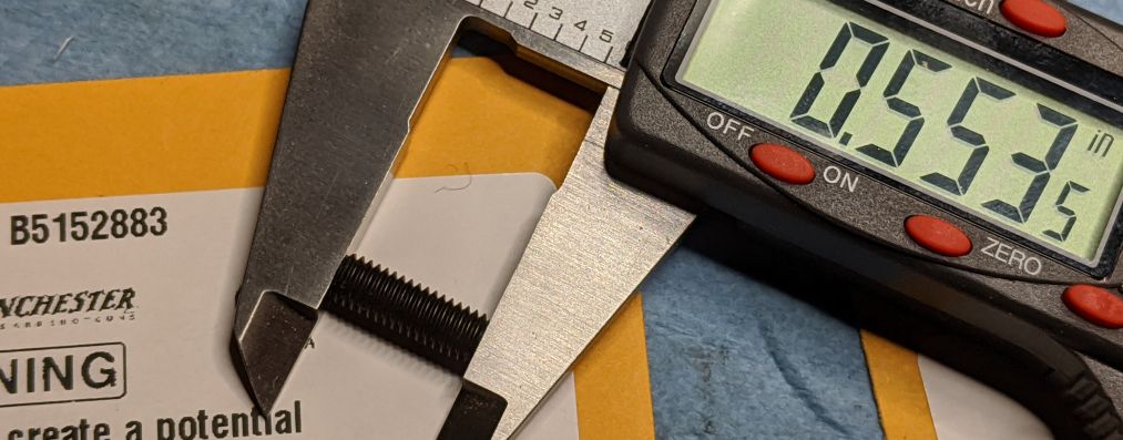
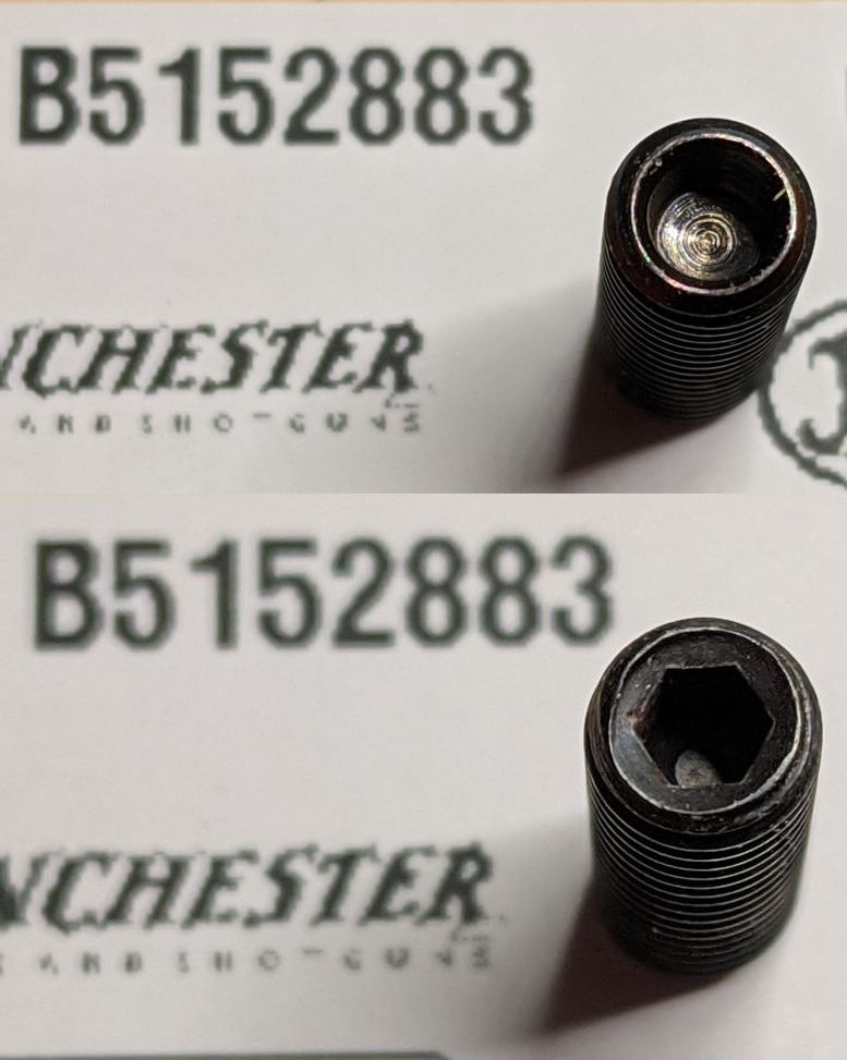
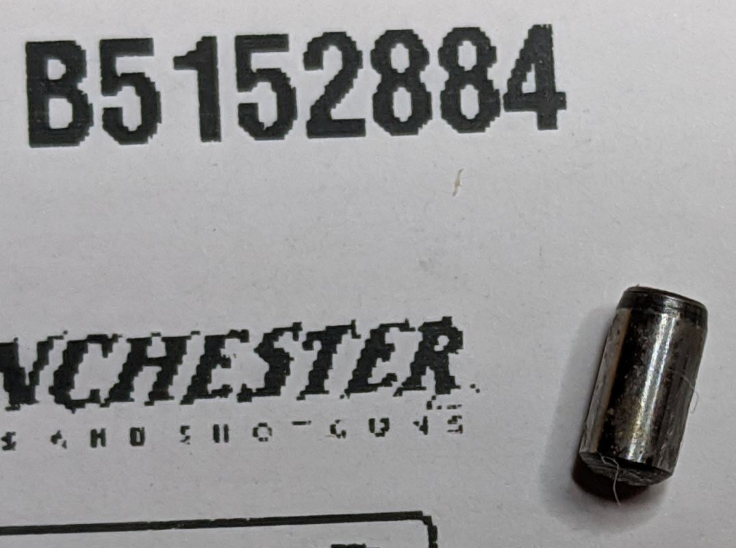
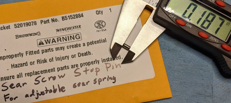
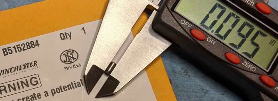
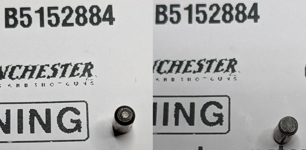
Sear spring adjusting screw and stop pin- Information |
||
|---|---|---|
The sear spring adjusting screw is used to adjust the trigger pull weight by pre-loading the sear spring.
The stop pin is a tiny pin, set into the frame, that prevents the user from backing the screw out too far, and would also prevent it from falling/shaking out while using the gun.
NOTE: I did not remove the sear spring adjusting screw, or it's stop pin. Since there is no hole in the frame to drive the stop pin out, I didn't see a practical way to remove the pin without buggering it. The screw cannot be backed out without removing the pin. The screw cannot be driven forward through the frame because the part around the head is not threaded. So I didn't remove them. |
Sear Spring Adjusting Screw (B5152883)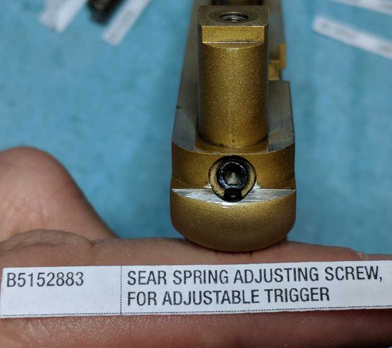 Sear Screw Stop Pin (B5152884) 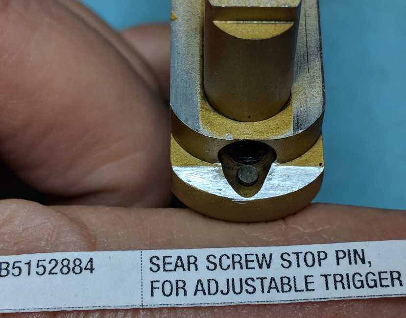 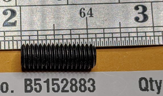
|
|
Magazine Disassembly and Reassembly |
||
|---|---|---|
|
Magazine disassembly
This is most easily done with a metal rod, such as a 7/64" or 3mm hex key, plus a punch 3/32"
Use the button to push the follower all the way down, and hold it there by putting the rod through the center slot above the follower
Use the punch (size 3/32") to push the button out of the follower, from right to left
Allow the rod above the follower to be pushed to the top of the center slot
Put the punch through the button hole, and pull the follower down a bit to release pressure on the rod
Remove the rod, place your finger over the top of the magazine, and allow the follower to move up against your finger
Remove the punch from the button hole, and then slowly lift your finger to release the remaining spring pressure
Remove follower by pulling it up out of the magazine body (the spring may or may not come with it)
Remove spring - if it does not fall free, use the rod to push it out
Cleaning the magazine
Magazines get dirty because debris falls into them while the slide is cycling
Check the inside front of the magazine for bullet lube build-up (clean with cotton swab)
include picture(s) of cleaning the spring
long (6") q-tips can be helpful for cleaning the inside bottom of the mag
spray cleaners, like Gun Scrubber or non-chlorinated brake cleaner work well on the mag body, too
be wary of using lube, such as oil, that will mix with fouling to form sludge... use dry lube instead
Magazine Reassembly
As with disassembly, this is most easily done with a 3/32" punch and a metal rod, such as a 7/64" or 3mm hex key
Drop spring into magazine body (either end first, doesn't matter)
Insert follower, top up, rounded end towards the front, placing the follower onto the spring
Push the follower down until the button hole is visible in the center slot of the magazine body
Put the punch through the button hole and use it to pull the follower down until there is space above the follower visible in the center slot
Put the metal rod through the center slot above the follower, and now use the rod to hold the follower down
Remove the punch from the button hole
Push follower all the way down until the hole in the follower is lined up with the bottom of the slot, and hold it there
Push the button into the follower, from left to right
Make sure it is all the way in, flush with the right side of the follower
Holding the follower down with the button, remove the metal rod from the center slot
Gently allow the spring to push the follower to the top of the magazine
|
Add Photo Hold follower down Add Photo Push out button Add Photo cleaning the spring Add Photo Magazine Body (B5152605) Add Photo Magazine Follower (B5152673) Add Photo Magazine Button (B5152672) Add Photo Magazine Spring (B5152677) |
|